
A motor end cover and method fixed by positioning pins

A technology of motor end cover and positioning pin, which is applied in the field of motor end cover installation and motor stator stamping. It can solve the problems of motor shaft bending deformation, motor radial size reduction, and acceleration bearing damage, etc., to achieve uniform and reduced electromagnetic air gap. Low processing cost and low noise

Active Publication Date: 2018-01-23
CHONGQING UNIV
View PDF4 Cites 0 Cited by
  • Summary
  • Abstract
  • Description
  • Claims
  • Application Information

AI Technical Summary

Problems solved by technology

[0016] The purpose of the present invention is to solve the problem that when the design of electric motors (especially with 2-pole asynchronous motors) tends towards high power and small volume development, the radial dimension of the motor is reduced, the length of the iron core is increased, the shaft of the motor is more and more slender, and the critical speed of the shaft is reduced. It often becomes the working speed of the motor. Due to the traditional stator structure and assembly, the unilateral magnetic pull of the motor increases, which will cause the deflection of the shaft to increase with the increase of the stiffness of the magnetic pull. The motor shaft is bent and deformed, and the damage to the bearing is accelerated. , causing vibration and noise, resulting in increased loss and reduced efficiency. In severe cases, the stator and rotor may even rub against each other, and the motor cannot rotate until the motor is burned. At the same time, it will cause problems such as increased vibration and noise.

Method used


Image

  • A motor end cover and method fixed by positioning pins
  • A motor end cover and method fixed by positioning pins
  • A motor end cover and method fixed by positioning pins

Examples


Embodiment 1

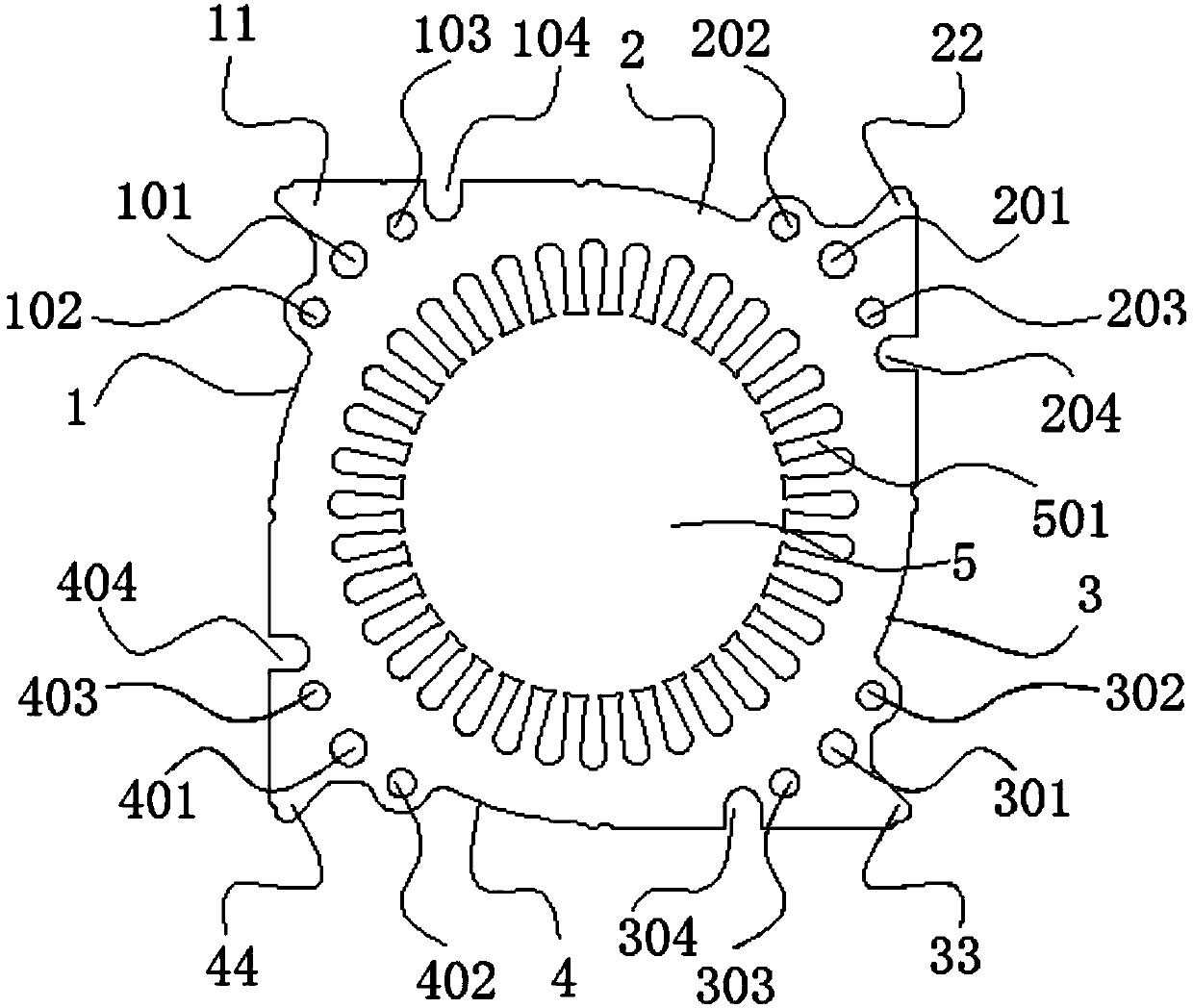
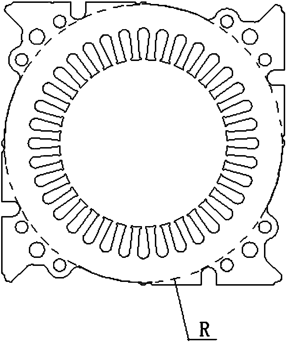
[0044] see figure 1 and 2 , the present embodiment discloses a stator punching sheet of a motor, and the center of the stator punching sheet has a central through hole 5 . The outer contour of the stator punch includes four concentric arc segments. The four concentric arcs are respectively arc segment I1, arc segment II2, arc segment III3 and arc segment IV4.

[0045] Such as figure 2 As shown by the dotted line, arc segment I1, arc segment II2, arc segment III3 and arc segment IV4 are on the same circle (hereinafter referred to as circle o), and any two adjacent arc segments The distance between them is equal.

[0046] Between the arc segment I1 and the arc segment II2 is a sharp corner portion I11. Between the arc segment II2 and the arc segment III3 is a sharp corner part II22. Between the arc segment III3 and the arc segment IV4 is a sharp corner portion III33. Between the arc segment IV4 and the arc segment I1 is a sharp corner part IV44. same as figure 2 As sh...

Embodiment 2

[0060] This embodiment discloses an installation method of a motor end cover fixed by positioning pins:

[0061] 1) Prepare two motor end covers 6, four to eight positioning pins 7, and several pieces of punched motor stator sheets as described in Embodiment 1.

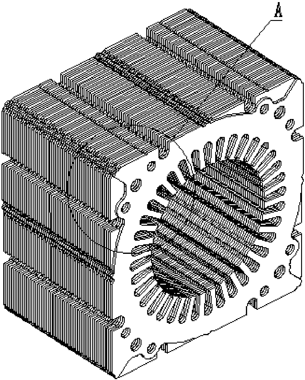
[0062] 2) The stator punches are stacked together to form a stator core, wherein any two adjacent stator punches are mirror images of each other. The screw holes on the stator punch overlap to form the screw holes of the stator core. The pin holes on the stator punch overlap to form the positioning holes of the stator core.

[0063] 3) The two motor end covers 6 are respectively placed at both ends of the stator core. Each of the four corners of the motor end cover 6 has a screw hole 601 and a pin hole 602 respectively.

[0064] 4) After inserting a positioning pin 7 from any pin hole 602, it is inserted into the pin hole of the stator core. Locating pin 7 and the positioning hole on the stator punching sheet are ...


PUM


Abstract

The invention provides a motor end cap fixed by positioning pins and a method. According to the scheme, the motor end cap, the positioning pins, a stator punch and positioning holes are used. The end cap has a supporting effect; a plurality of positioning holes are uniformly distributed in the end cap; the stator punch also has a supporting and fixing effect; positioning holes are also uniformly distributed in the stator punch; the number of the positioning holes of the stator punch is the same with that of the positioning holes of the end cap; and the positioning pins enter the positioning holes of the motor end cap and the positioning holes of the stator punch (3) in a punching manner. The motor end cap is simple in structure and convenient to operate; the motor end cap and the stator punch are machined into required structures; and the positioning pins are punched into the positioning holes of the motor end cap and the positioning holes of the stator punch by effects of an external power source, so that the motor end cap and the stator punch are fastened together in a punching manner. Materials are saved, the assembling efficiency of a motor is improved, the machining cost is reduced, the coaxility and the accuracy of the motor can be ensured after the motor is assembled, electromagnetic air gas of the motor are uniform, and noises are small.

Description

technical field [0001] The invention relates to the field of electric vehicle motors, in particular to a motor stator stamping and a motor end cover installation method fixed by positioning pins. Background technique [0002] Existing industrial fields, including the field of electric vehicles, require a large number of motors. The traditional motor assembly method is mainly installed by means of screws and end caps. The traditional screw motor assembly operation is to pass the screw through the end cover hole, put on the flat washer, spring washer, and nut. The dimensions of these four parts are relatively small, and it is extremely difficult to assemble the motor; and each set of screws, flat washer , Spring washers, and nuts need to be tightened with an electric wrench, because it needs to be tightened manually by groups, and the force is inconsistent, so the installation accuracy cannot be guaranteed after tightening, so the coaxiality of the motor is not good, and the n...

Claims


Application Information

Patent Timeline
Patent Type & Authority Patents(China)
IPC IPC(8): H02K1/12H02K5/04H02K15/02H02K15/00
CPCH02K1/12H02K5/04H02K15/00
Inventor 刘和平刘静张煜昕刘庆涂郁潇颖邓力余传祥郑群英
Owner CHONGQING UNIV
Learn More