Angle regulating device and application thereof

A technology of an angle adjustment device and an adjustment seat, which is applied in the directions of identification devices, pivot connections, instruments, etc., can solve the problem that the angle between the box and the box or the unit and the unit cannot be adjusted according to the needs, and achieve the effect of rapid adjustment.

Active Publication Date: 2015-07-01
CREATELED ELECTRONICS
View PDF6 Cites 6 Cited by
  • Summary
  • Abstract
  • Description
  • Claims
  • Application Information

AI Technical Summary

Problems solved by technology

[0002] At present, large-scale LED displays are generally formed by assembling multiple boxes or unit boards. During the assembly process, the boxes are assembled on the same plane between the boxes or between the units. After the assembly is completed, the box and box Angles between volumes or between elements cannot be adjusted as desired

Method used


Image

  • Angle regulating device and application thereof
  • Angle regulating device and application thereof
  • Angle regulating device and application thereof

Examples


no. 1 example

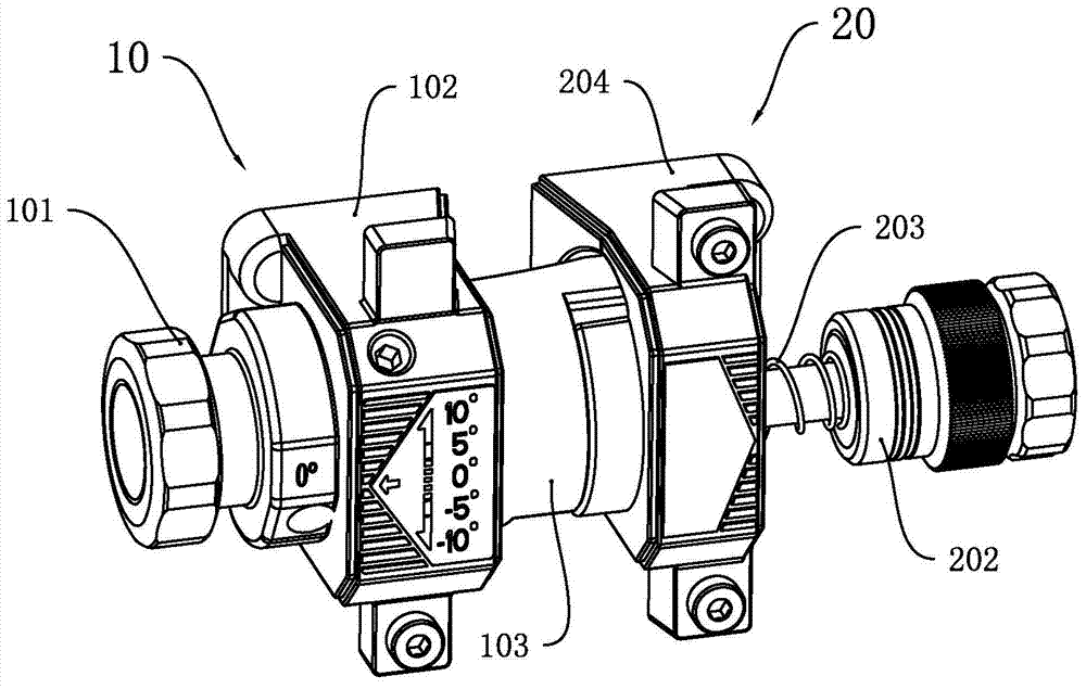
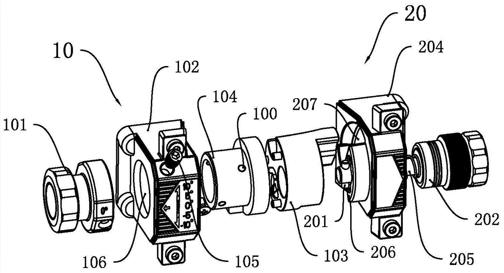
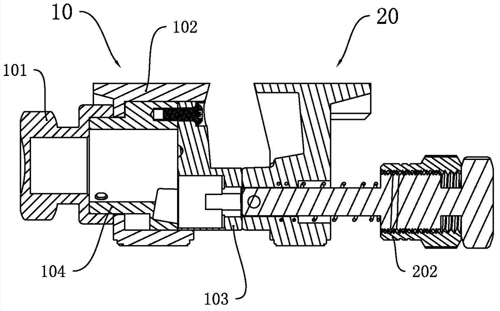
[0039] The first embodiment, such as Figure 1 to Figure 7 As shown, an angle adjustment device includes a main adjustment member 20 , a secondary adjustment member 10 and a positioning member 105 .

[0040] like figure 2 , Figure 5 and Image 6 As shown, the main adjustment member 20 includes a connecting rod and a first support 204 with a first contact surface 206 on one end surface, and a first support 204 extending from the first contact surface 206 of the first support 204 to the other surface of the first support. There is a first connection hole 208 . The connecting rod includes a screw 205 with external threads, a nut 202 with internal threads and a first compression spring 203 . One side of the first support 204 is provided with a first contact surface 206 and several accommodating grooves 207, and the other side is a plane; the first contact surface 206 of the first support 204 runs through the plane of the first support 204 A first connection hole 208 is prov...

no. 2 example

[0048] The second embodiment, the difference between this embodiment and the first embodiment: the three second contact surfaces 107 and the axis of the adjustment column 103 are in sequence 90 degrees, plus 85 degrees and minus 85 degrees.

no. 3 example

[0049] In the third embodiment, the connecting rod is a screw with external threads, and the first connecting hole is provided with internal threads that match the screw; the second connecting hole is provided with internal threads that match the screw; adjust the first contact surface and One of the second contact surfaces is in close contact, and the connecting rod passes through the first connection hole and the second connection hole corresponding to the second contact surface in sequence and is used to fix the first support and the second support.

[0050] Adjust the alignment of the first connecting hole with the second connecting hole corresponding to a certain second contact surface, the screw rod passes through the first connecting hole and the second connecting hole, and is fixedly connected with the first support and the second support. When the first contact surface is in close contact with the second contact surface, the main adjustment part and the auxiliary adjus...


PUM


Abstract

The invention discloses an angle regulating device which comprises a main regulating part, an auxiliary regulating part and a positioning part, wherein the main regulating part comprises a connection rod and a first supporting base, one end surface of the first support base is provided with a first contact surface, a first connection hole is formed between the first contact surface of the first supporting base and the other surface of the first supporting base in a penetrating manner, the auxiliary regulating part comprises a second supporting base which is provided with a through hole in a penetrating manner and a regulating base which is arranged in the through hole and can freely rotate in the through hole; one end of the regulating base is divided into a plurality of second contact surfaces, the second contact surfaces and the axis of the regulating base form different angles, and the regulating base is provided with second connection holes which are vertical to the second contact surfaces; the positioning part is used for positioning the first connection hole and the second connection holes and positioning the regulating base, the first contact surface is adjusted so as to be closely contacted with the second contact surfaces, and the connection rod successively passes through the first connection hole and the second connection holes which correspond to the second contact surfaces and used for fixing the first supporting base and the second supporting base. The angle regulating device has the advantages of conveniently and rapidly adjusting the angle between a male lock and a female lock.

Description

technical field [0001] The invention relates to an angle adjuster, in particular to an angle adjustment device and its application. Background technique [0002] At present, large-scale LED displays are generally formed by assembling multiple boxes or unit boards. During the assembly process, the boxes are assembled on the same plane between the boxes or between the units. After the assembly is completed, the box and box Angles between volumes or between elements cannot be adjusted as desired. For this reason, the inventor has designed an angle adjustment device that can easily and quickly adjust the angle between the LED boxes. Contents of the invention [0003] The purpose of the present invention is to solve the deficiencies of the prior art, and provide an angle adjustment device and its application. [0004] A kind of technical scheme of the present invention: [0005] An angle adjustment device, comprising: a main adjustment member, an auxiliary adjustment member ...

Claims


Application Information

Patent Timeline
Patent Type & Authority Applications(China)
IPC IPC(8): F16C11/04F16C11/10G09F9/33
Inventor 郭富荣张海军涂江波阳海军
Owner CREATELED ELECTRONICS
Why Eureka
Try Eureka