Method for determining surface waveguide dead zone information based on ray tracing

A surface waveguide and ray tracing technology, applied in radio wave measurement systems, using re-radiation, radio wave reflection/re-radiation, etc., can solve the problems of lack of quantitative calculation and analysis, and stay in the description of existence.

Inactive Publication Date: 2015-07-08
XIDIAN UNIV
View PDF2 Cites 2 Cited by
  • Summary
  • Abstract
  • Description
  • Claims
  • Application Information

AI Technical Summary

Problems solved by technology

[0003] At present, the analysis of the electromagnetic blind zone of the tropospheric atmospheric duct at sea is mainly for the evaporation duct, and the ana

Method used


Image

  • Method for determining surface waveguide dead zone information based on ray tracing
  • Method for determining surface waveguide dead zone information based on ray tracing
  • Method for determining surface waveguide dead zone information based on ray tracing

Examples


Embodiment Construction

[0025] In order to make the above and other objects, features and advantages of the present invention more apparent, the following specifically cites the embodiments of the present invention, together with the accompanying drawings, for a detailed description as follows.

[0026] In the following description, a lot of specific details are set forth in order to fully understand the present invention, but the present invention can also be implemented in other ways different from those described here, and those skilled in the art can do it without departing from the meaning of the present invention. By analogy, the present invention is therefore not limited to the specific examples disclosed below.

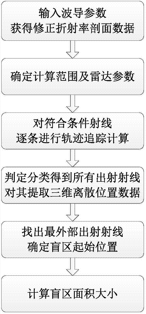
[0027] combine figure 1 Shown, the inventive method comprises the following steps: transmitting antenna sends out ray,

[0028] Step 1. Obtain the modified refractive index profile data;

[0029] Obtain four basic input parameters of the surface waveguide according to the surface w...


PUM


Abstract

The invention discloses a method for detecting surface waveguide dead zone information based on ray tracing. The method includes the following steps that modified refractive index profile data are obtained; the calculating range including the maximum spreading distance, the largest spreading height, the height stepping value, the transmitting antenna height, the transmitting antenna initial transmitting elevation and the ray elevation interval is determined, whether rays are tracked or not is judged; the rays are tracked according to the second-order Taylor approximation mode of the Snell law, and the spreading track of each ray is obtained; whether the rays conforming to the tracking conditions are trapped or not is judged, the rays are classified, and discrete data of the rays which are transmitted out are extracted; initial position parameters of a waveguide top dead zone are obtained; the area of the surface waveguide top dead zone is calculated. According to the method for detecting the surface waveguide dead zone information based on ray tracing, a ray tracking method is introduced to judge and classify the radio wave rays, extracting and data discretization are conducted, the initial position and range of the dead zone are simply, visually and accurately obtained, the complexity of a dead zone calculating model is lowered, and therefore the area of the convection zone surface waveguide dead zone is fast calculated.

Description

technical field [0001] The invention relates to radar detection and electric wave propagation calculation, in particular to a calculation method for determining the blind area of ​​a surface waveguide. Background technique [0002] The actual detection of radar is subject to factors such as its working system, signal detection capability, antenna type, etc., and there will be certain electromagnetic blind spots. At the same time, different detection environments will also affect its electromagnetic blind zone. This is especially evident in the low-altitude tropospheric marine atmospheric environment. Due to the extreme anomaly of the refractive index gradient at the bottom of the troposphere above the sea, an atmospheric waveguide will be formed, so that a part of the radio wave is trapped in the waveguide layer, the loss is reduced, and it propagates to areas that cannot be detected originally, forming trans-horizon propagation. But on the other hand, it will change the n...

Claims


Application Information

Patent Timeline
IPC IPC(8): G01S13/06
CPCG01S7/40
Inventor 张沛白璐吴振森曹云华李正军
Owner XIDIAN UNIV
Why Eureka
Try Eureka