
Array substrate and liquid crystal display equipment

A technology of array substrates and substrates, applied in nonlinear optics, instruments, optics, etc., can solve problems such as difficult to observe images visually, and achieve the effect of reducing dependence on

Active Publication Date: 2015-07-08
TCL CHINA STAR OPTOELECTRONICS TECH CO LTD
View PDF5 Cites 4 Cited by
  • Summary
  • Abstract
  • Description
  • Claims
  • Application Information

AI Technical Summary

Problems solved by technology

[0003] When viewing a liquid crystal display device with polarized sunglasses outdoors, only when the light transmission axis of the liquid crystal display device is the same as that of the polarized sunglasses can the image on the liquid crystal display device be effectively observed; the traditional fringe field switch (Fringe In Field Switching (FFS for short) mode, the pixel electrode is designed as a rectangle with one side parallel to the X axis, and the light transmission axis of the pixel area extends parallel to the long side or short side of the pixel electrode, and the transmission axis of the liquid crystal display device sometimes changes The transmission axis of the polarized sunglasses does not match, making it difficult to visually observe the image displayed by the liquid crystal display device

Method used


Image

  • Array substrate and liquid crystal display equipment
  • Array substrate and liquid crystal display equipment
  • Array substrate and liquid crystal display equipment

Examples


Embodiment Construction

[0052] The present invention will be described in detail below in conjunction with the accompanying drawings and embodiments.

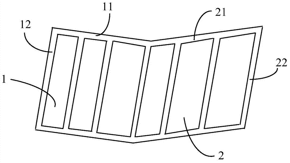
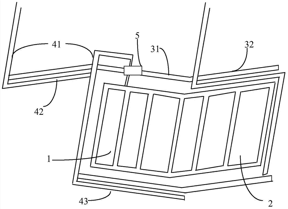
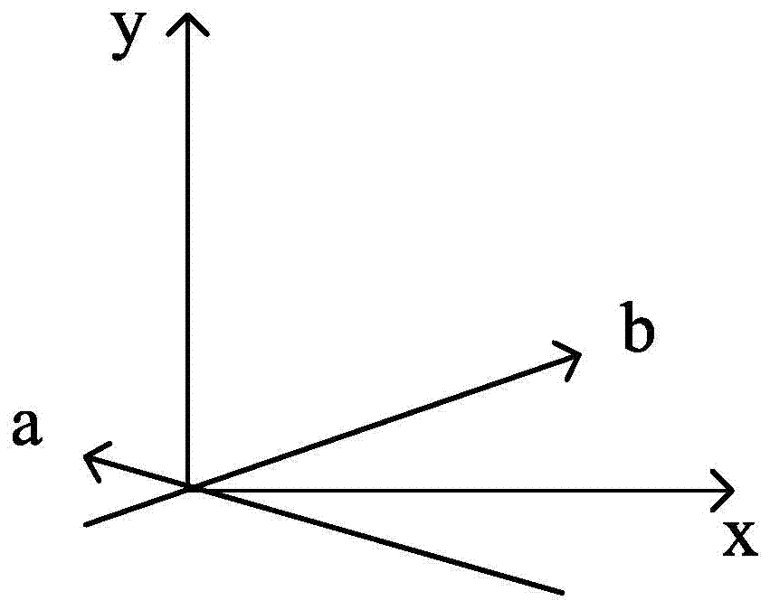
[0053] An embodiment of the present invention provides an array substrate. The array substrate is a rectangular substrate extending along the x-axis direction and the y-axis direction. parallel to the y-axis, wherein the array substrate includes a plurality of pixel electrodes, and the plurality of pixel electrodes are arranged on the array substrate, such as figure 1 , wherein each pixel electrode includes at least a first part 1 and a second part 2 respectively, wherein the first part 1 is arranged obliquely along a first direction, and the first direction is different from the x-axis direction and the y-axis direction, that is, the first direction is both Not parallel to the x-axis nor parallel to the y-axis, the first direction is inclined relative to the x-axis direction and has a first angle between the first direction and the x-axis direction, an...


PUM


Abstract

The invention discloses an array substrate and liquid crystal display equipment. The array substrate is a rectangular substrate extending along an x axis direction and a y axis direction, wherein the x axis direction is vertical with the y axis direction; the array substrate comprises a plurality of pixel electrodes; each pixel electrode comprises a first part and a second part; the first part is arranged along a first direction in an inclined manner; the first direction is different from the x axis direction and the y axis direction; the second part is arranged along the second direction in the inclined manner; the second direction is different from the x axis direction, the y axis direction and the first direction. With the adoption of the manner, the visibility of an image on the liquid crystal display equipment when users watch the liquid crystal display equipment with polarized sunglasses can be improved, and the dependence on the viewing angle is reduced.

Description

technical field [0001] The invention relates to the technical field of liquid crystal displays, in particular to an array substrate and a liquid crystal display device. Background technique [0002] In a liquid crystal display device, the configuration of a liquid crystal panel is, for example, an active matrix type including a TFT (Thin Film Transistor) array substrate having a pixel area, a color filter substrate opposite to the TFT array substrate, and a TFT array substrate and a color filter substrate between the TFT array substrate and the color filter substrate. The liquid crystal layer provided between the filter substrates forms a plurality of thin film transistors that function as pixel switching elements in the pixel area; in an active matrix type liquid crystal panel, by inputting a voltage from the pixel switching element to the pixel electrode, An electric field is generated between the electrodes and the common electrode and applied to the liquid crystal layer ...

Claims


Application Information

Patent Timeline
Patent Type & Authority Applications(China)
IPC IPC(8): G02F1/1343
CPCG02F1/134309G02F1/134336G02F1/136286G02F1/134345G02F1/134372G02F1/133514G02F1/13439G02F1/1368G02F2201/121G02F2201/123
Inventor 邓竹明
Owner TCL CHINA STAR OPTOELECTRONICS TECH CO LTD
Learn More