Centrifugal pump

A centrifugal pump and pump casing technology, applied in the field of centrifugal pumps, can solve the problems of low operating efficiency and large useless work, and achieve the effect of improving operating efficiency and eliminating eddy currents

Inactive Publication Date: 2015-07-15
CHANGSHA CC PAPER MACHINERY
View PDF5 Cites 0 Cited by
  • Summary
  • Abstract
  • Description
  • Claims
  • Application Information

AI Technical Summary

Problems solved by technology

Due to the large amount of useless work consumed by the vortex flow, the operating efficiency of this type of pump is very low
This phenomenon is very serious for pumps with high lift and small flow, so their operating efficiency is extremely low

Method used


Image

  • Centrifugal pump
  • Centrifugal pump
  • Centrifugal pump

Examples


Embodiment Construction

[0026] The present invention will be further described in detail below in conjunction with the accompanying drawings and specific embodiments.

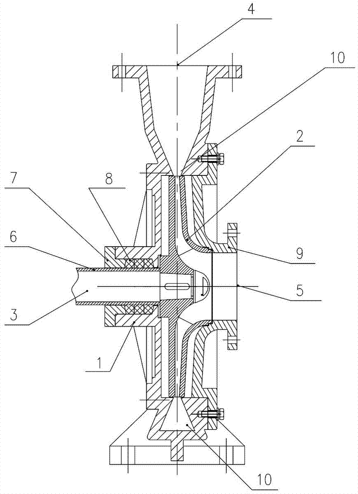
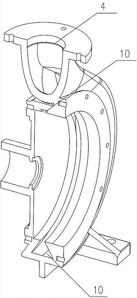
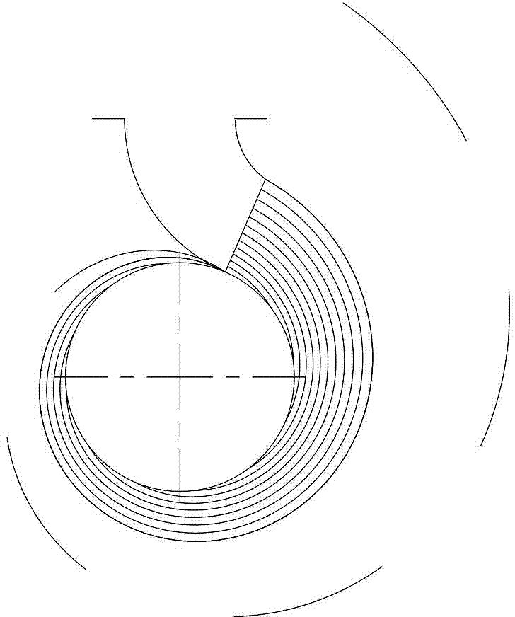
[0027] Such as Figure 1 to Figure 5 As shown, the centrifugal pump of the present invention includes a pump casing 1 and an impeller 2 installed in the pump casing 1, the impeller 2 is connected with the main shaft 3, and rotates under the driving of the main shaft 3 and the driving parts; the top of the pump casing 1 is provided with The water outlet 4 is provided with a water inlet 5 on the side of the pump casing 1 , and the working surface of the impeller 2 faces the water inlet 5 . The impeller 2 includes several blades 201 , and an impeller flow channel 202 is formed between adjacent blades 201 . In the present invention, the annular channel 10 in the pump casing 1 has a trapezoidal cross-section, that is, forms an annular gradually expanding trapezoidal channel, and the small side of the trapezoid in the trapezoidal cross-sec...


PUM


Abstract

The invention discloses a centrifugal pump. The centrifugal pump comprises a pump shell and an impeller arranged in the pump shell, wherein the impeller comprises a plurality of blades; impeller flow channels are formed between adjacent blades; an annular flow channel in the pump shell has a trapezoidal section; the narrow edge of the trapezoid in the trapezoidal section of the annular flow channel is equal to the outlet width of the impeller flow channel. The centrifugal pump has the advantages of simple and compact structure, removal of eddy current formed in the flow channel of the pump, increase in the overall efficiency of the pump, and the like.

Description

technical field [0001] The invention mainly relates to the field of centrifugal pump equipment for transporting liquid, in particular to a centrifugal pump. Background technique [0002] Centrifugal pumps are general-purpose equipment in all walks of life, with a wide range of applications, such as: centrifugal water pumps. At present, the existing high-lift and low-flow centrifugal pumps have very low operating efficiency and cause a lot of waste of energy. This phenomenon is due to the unreasonable structural design of the pump. [0003] Based on the theory of theoretical fluid dynamics, it can be deduced that for pumps with low efficiency, the movement of the fluid in the pump is not simple laminar flow or turbulent flow, but serious vortex flow, and eliminating such vortex flow can To a certain extent, the purpose of energy saving can be achieved at the same time. [0004] There is also serious vortex flow in the impeller channel of the centrifugal pump, because the fl...

Claims


Application Information

Patent Timeline
IPC IPC(8): F04D1/00F04D29/42F04D29/22F04D29/66
Inventor 陈永生陈瑜
Owner CHANGSHA CC PAPER MACHINERY
Why Eureka
Try Eureka