A pressure-discharging one-way valve and a water dispenser

A technology for one-way valves and water dispensers, applied in beverage preparation devices, household appliances, applications, etc., can solve the problems of occupying space, affecting the life of hot tanks, increasing product costs, etc., and achieve the effect of reducing product costs and saving internal space

Active Publication Date: 2018-03-20
SHENZHEN ANGEL DRINKING WATER IND GRP
View PDF7 Cites 0 Cited by
  • Summary
  • Abstract
  • Description
  • Claims
  • Application Information

AI Technical Summary

Problems solved by technology

[0002] Water dispenser in the prior art such as image 3 As shown, it includes a cold tank 100 and a hot tank 102. A one-way valve 103 is installed between the cold tank 100 and the hot tank 102. This check valve 103 can prevent the hot water in the hot tank 102 from flowing backwards. When 102 is in the water-filled state, if the heating is continued, the pressure in the hot tank 102 will be too high due to thermal expansion of the water and steam will be generated, and problems such as water spraying from the water outlet and poor water flow will be caused by excessive pressure during normal water intake. Under long-term use conditions, it not only affects the life of the hot tank, but also has the potential for bursting. In order to exhaust and relieve the pressure on the hot tank, a pressure relief pipe 104 is usually installed on the top of the hot tank 102 to facilitate the pressure relief of the hot tank 102. However, this structure Not only takes up space, but also increases product cost

Method used


Image

  • A pressure-discharging one-way valve and a water dispenser
  • A pressure-discharging one-way valve and a water dispenser
  • A pressure-discharging one-way valve and a water dispenser

Examples


Embodiment Construction

[0014] The present invention will be described in more detail below in conjunction with the accompanying drawings and embodiments.

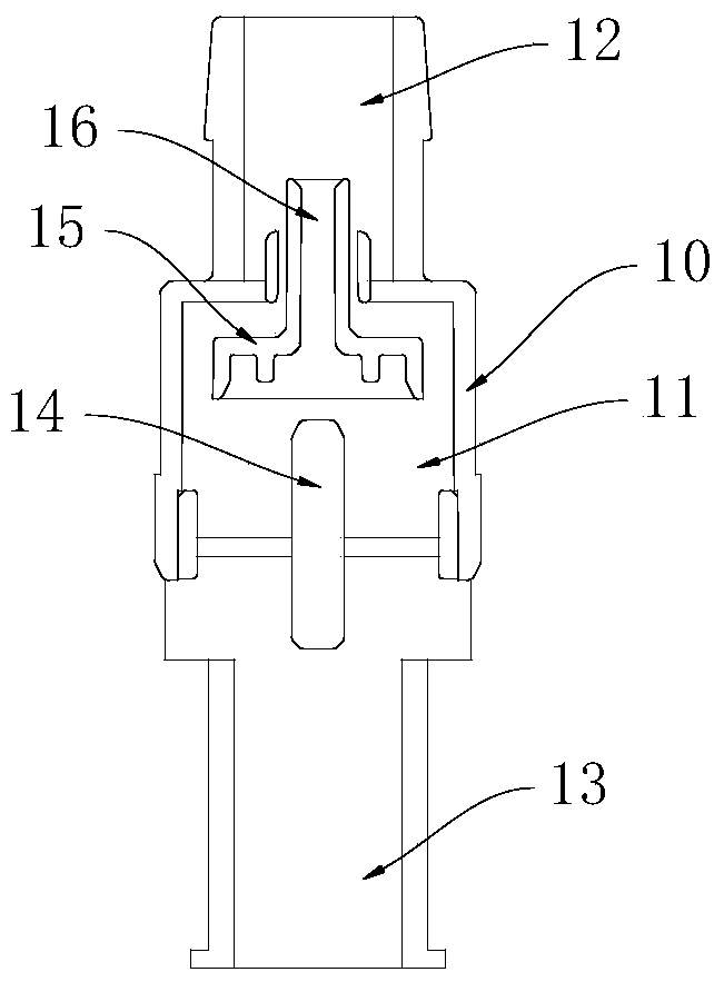
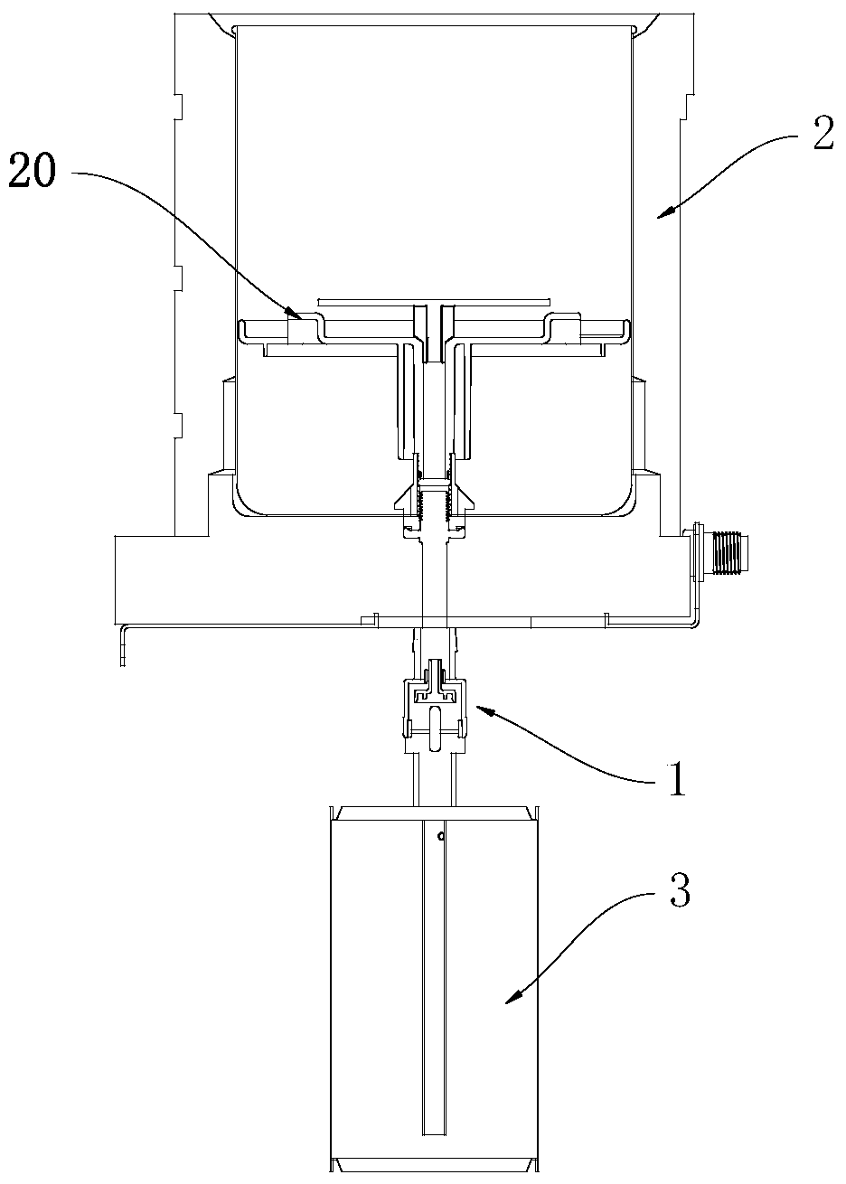
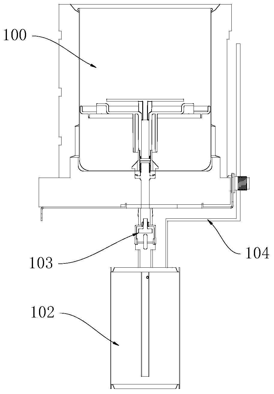
[0015] The invention discloses a pressure relief check valve, which combines figure 1 and figure 2 As shown, the pressure relief check valve 1 is installed between the cold tank 2 and the hot tank 3 of the water dispenser. The pressure discharge check valve includes a housing 10, and a cavity is formed in the housing 10. 11. The casing 10 is provided with a water inlet 12 and a water outlet 13 which are connected to the cavity 11, the water inlet 12 is connected to the cold tank 2, and the water outlet 13 is connected to the hot tank 3 , the cavity 11 is provided with a ejector rod 14 and a reciprocatingly slidable valve core 15, the ejector rod 14 is arranged between the valve core 15 and the water outlet 13, and the valve core 15 has a The pressure relief hole 16 at the end, wherein:

[0016] When the pressure of the pressure relief check ...


PUM


Abstract

The invention discloses a pressure-discharging one-way valve, which is installed between a cold tank and a hot tank of a water dispenser. The pressure-discharging one-way valve includes a casing, and a cavity is formed in the casing. A water inlet and a water outlet connected to the cavity are provided on the casing, the water inlet is connected to the cold tank, the water outlet is connected to the hot tank, and a ejector rod and a water outlet are arranged in the cavity. A reciprocating and slidable valve core, the ejector rod is arranged between the valve core and the water outlet, and the valve core is provided with a pressure relief hole running through both ends thereof, wherein: when the water pressure comes from the cold tank, the valve core It is separated from the water inlet, and the valve core abuts against the ejector rod; when the water pressure comes from the hot tank, the valve core is pressed against the water inlet, and the hot tank exhausts or releases pressure to the cold tank through the pressure discharge hole. The invention not only realizes the pressure discharge function, but also effectively saves the inner space of the water dispenser and reduces the product cost.

Description

technical field [0001] The invention relates to drinking water equipment, in particular to a pressure-discharging check valve and a water dispenser. Background technique [0002] Water dispenser in the prior art such as image 3 As shown, it includes a cold tank 100 and a hot tank 102. A one-way valve 103 is installed between the cold tank 100 and the hot tank 102. This check valve 103 can prevent the hot water in the hot tank 102 from flowing backwards. When 102 is in the water-filled state, if the heating is continued, the pressure in the hot tank 102 will be too high due to thermal expansion of the water and steam will be generated, and problems such as water spraying from the water outlet and poor water flow will be caused by excessive pressure during normal water intake. Under long-term use conditions, it not only affects the life of the hot tank, but also has the potential for bursting. In order to exhaust and relieve the pressure on the hot tank, a pressure relief pip...

Claims


Application Information

Patent Timeline
Patent Type & Authority Patents(China)
IPC IPC(8): A47J31/46A47J31/00A47J31/44
Inventor 张发余伟良
Owner SHENZHEN ANGEL DRINKING WATER IND GRP
Why Eureka
Try Eureka