Process and device for the control of the rudder of an aircraft

a technology for aircraft rudders and control surfaces, applied in process and machine control, actuation personally, instruments, etc., can solve problems such as mechanical backup, mechanical failure of all controls, and unfavorable control precision of mechanical transmission systems

Inactive Publication Date: 2001-03-27
SOC NATIONALE INDUSTRIELLE AEROSPATIALE SA
View PDF7 Cites 40 Cited by
  • Summary
  • Abstract
  • Description
  • Claims
  • Application Information

AI Technical Summary

Benefits of technology

Such a hydraulic generating system equips the hydrostatic actuators. It makes it possible to free the operation of the actuator from that of an engine.

Problems solved by technology

Thus, friction and any deformation of the mechanical transmission system unfavourably influences the precision of the controls.
However, such a device has no mechanical backup in the case of an electric fault leading to the failure of all the controls.
It therefore constitutes a mechanical backup in the case of an electric failure to the other control systems.
A failure or stoppage of one of the engines can lead to a pressure loss in the hydraulic circuit associated therewith and consequently the corresponding actuator is rendered inoperative.
The failure of one of the engines, particularly in the case where the aircraft has its engines fixed to the wings, can lead not only to a pressure loss in the hydraulic circuit associated therewith, but more particularly leads to a thrust unbalance, the thrust no longer being symmetrical.
However, when it is necessary to compensate a thrust unbalance of the engines, particularly in the take-off phase, maximum loads are exerted on the rudder and said loads condition the size of the actuators to be used.
Thus, as it is not possible to simultaneously operate the rudder with a hydromechanical actuator and an electro-hydraulic actuator on equipment equipped with a rudder control device according to document (1), the actuators and associated hydraulic circuits must be dimensioned in such a way that each actuator is able to exert on the rudder the maximum forces or loads necessary for compensating an asymmetrical thrust in the case of a failure of one of the engines.
Such a measure leads to an increase in the size and consequently the weight of the actuators and the corresponding hydraulic circuits.
The aforementioned problem not only arises for the rudder, but also for the other control surfaces of the aircraft.
The other control surfaces of an aircraft such as the inclination or pitch control surfaces (elevators) are certainly less sensitive than the rudder to thrust instability resulting from an engine failure, but can also be subject to occasional high loads.

Method used


Image

  • Process and device for the control of the rudder of an aircraft
  • Process and device for the control of the rudder of an aircraft
  • Process and device for the control of the rudder of an aircraft

Examples


first embodiment

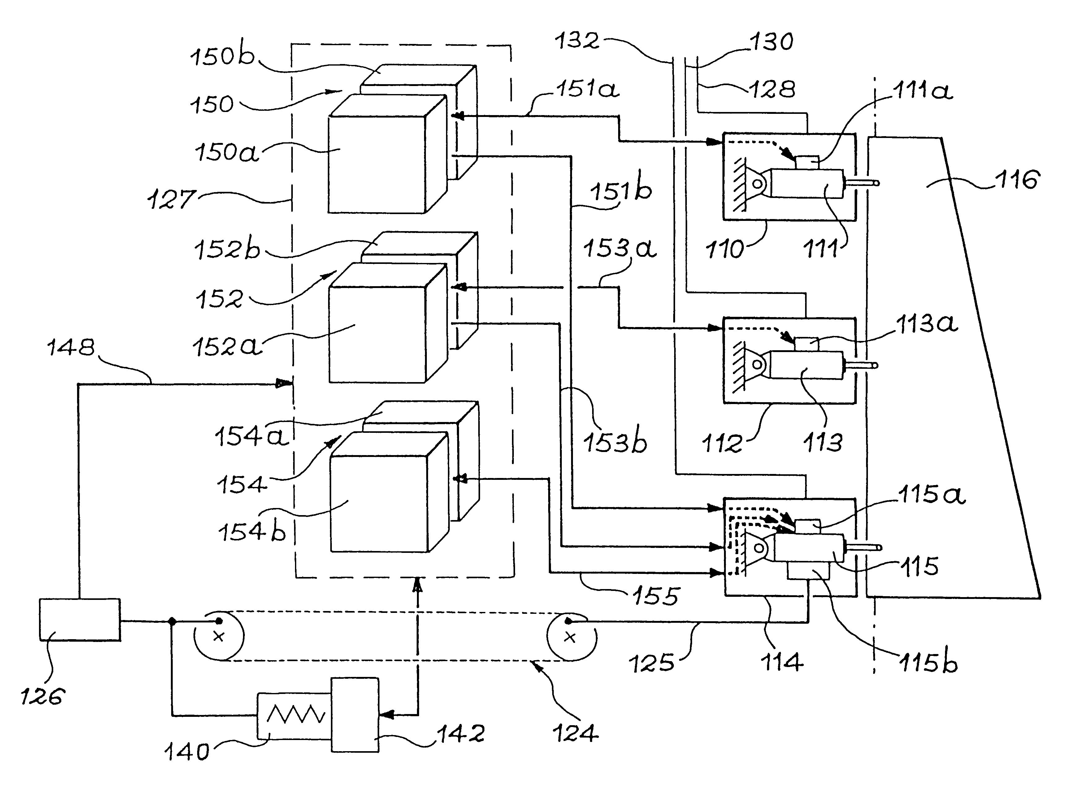
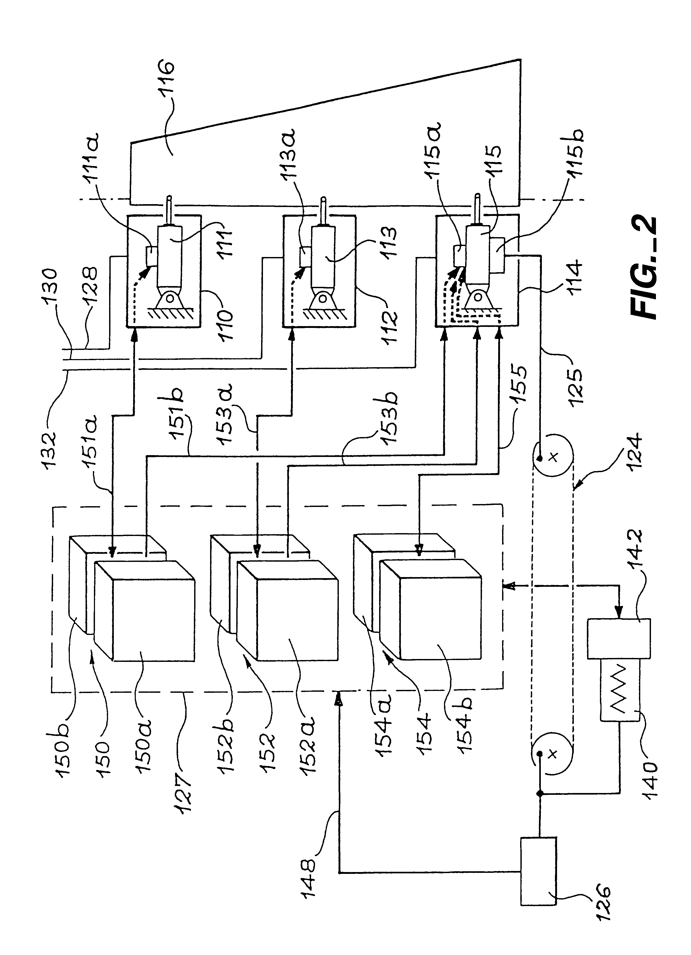
FIG. 2 is a simplified diagrammatic representation of a control surface control device according to the invention.

FIG. 3 is a simplified diagrammatic representation of a actuator having an electric control input able to equip the device of FIG. 2.

FIG. 4 is a simplified diagrammatic representation of a mixed actuator able to equip the device of FIG. 2.

FIG. 5 is a simplified diagrammatic representation of another type of mixed actuator able to equip the device of FIG. 2.

second embodiment

FIG. 6 is a simplified diagrammatic representation of a control surface control device according to the invention.

third embodiment

FIG. 7 is a simplified diagrammatic representation of a control surface control device according to the invention.

DESCRIPTION OF EMBODIMENTS OF THE INVENTION

In the following description, identical or similar components in the different drawings carry the same references in order to facilitate the understanding thereof.

FIG. 2 shows in simplified form a first embodiment of the rudder control device according to the invention, which has three actuators 110, 112 and 114 equipped with jacks 111, 113 and 115 for manipulating a control surface 116. The actuators 110 and 112 have electric control inputs 111a and 113a and the actuator 114 is a mixed actuator having an electric control input 115a and a mechanical control input 115b. The actuators are of the "single body" type, i.e. each actuator is connected to a single hydraulic circuit and only has one jack.

The jack of each of the actuators is supplied by a different hydraulic circuit. The hydraulic circuits of jacks 111, 113 and 115 are pa...


PUM


Abstract

A device for the control of a control surface of an aircraft has at least two actuators (110, 112, 114), each having at least one electric control input (111a, 113a, 115a). At least one of the actuators (115), called the mixed actuator, also has a mechanical control input (115b), and an electric control system for the actuators is able to occupy a state corresponding to a fault of an engine in which at least two of the actuators simultaneously operate the control surface and a state corresponding to an electric fault, in which the mixed actuator (115) operates the control surface from the mechanical control input.

Description

DESCRIPTION1. Technical Field of the InventionThe present invention relates to a process and a device for the control of a control surface of an aircraft.The invention more particularly relates to an electric control device intended for transport aircraft simultaneously satisfying the requirements of precision, reliability and lightness existing for such equipment.2. Prior ArtFIG. 1 diagrammatically illustrates a known control device of the type presently equipping AIRBUS aircraft A320 and A340. This device comprises an arrangement of three actuators 10, 12, 14 for operating a rudder 16. The three actuators are of the hydromechanical type and each has a mechanical control input 18, 20, 22. Their control is ensured by a linkage 24, which acts on mechanical control inputs 18, 20, 22 and which can be operated from pedals 26 (rudder bar). In addition, each actuator 10, 12, 14 is supplied by a different hydraulic circuit 28, 30, 32 supplying the energy necessary for the movement of the r...

Claims


Application Information

Patent Timeline
Patent Type & Authority Patents(United States)
IPC IPC(8): B64C13/00B64C13/42B64C13/50G05D1/00
CPCB64C13/42B64C13/503G05D1/0055G05D1/0077Y02T50/44B64C13/504Y02T50/40
Inventor GAUTIER, JEAN-PIERREORTEGA, JEAN-MARC
Owner SOC NATIONALE INDUSTRIELLE AEROSPATIALE SA
Why Eureka
Try Eureka