
Multi-cluster processor operating only select number of clusters during each phase based on program statistic monitored at predetermined intervals

a multi-cluster processor and cluster technology, applied in the direction of multiple processing units, instruments, sustainable buildings, etc., can solve the problem of fine-grained reconfiguration opportunities missed by algorithms, and achieve the effect of improving the processor's ability to support multiple threads, improving single-threaded performance, and saving leakage energy

Active Publication Date: 2009-02-10
UNIVERSITY OF ROCHESTER
View PDF6 Cites 39 Cited by
  • Summary
  • Abstract
  • Description
  • Claims
  • Application Information

AI Technical Summary

Benefits of technology

The present invention is a dynamically tunable clustered architecture that optimizes the communication-parallelism trade-off for improved single-threaded performance in the face of trends. By employing only a subset of the total number of available clusters for the thread, the balance is effected by identifying the optimal number of clusters for a program phase and matching the hardware to the program's requirements. The result is improved performance and efficiency in both single-threaded and multi-threaded workloads. The invention also provides opportunities for disabling entire clusters or dedicated them to specific threads, thereby simultaneously achieving the goals of optimal single and multithreaded throughput. The invention is applicable to almost every program and yields average performance improvements of 11% over the base architecture. The invention also incorporates the importance of a variable-length instruction interval and fine-grained reconfiguration at branch boundaries. Overall, the clustered processor model exposes a clear trade-off between communication and parallelism, and it readily lends itself to low-cost reconfiguration.

Problems solved by technology

However, such an algorithm misses fine-grained opportunities for reconfiguration, and we present alternative techniques that invest more hardware in an attempt to target these missed opportunities.

Method used


Image

  • Multi-cluster processor operating only select number of clusters during each phase based on program statistic monitored at predetermined intervals
  • Multi-cluster processor operating only select number of clusters during each phase based on program statistic monitored at predetermined intervals
  • Multi-cluster processor operating only select number of clusters during each phase based on program statistic monitored at predetermined intervals

Examples


Embodiment Construction

[0032]A preferred embodiment of the present invention and variations thereon will be described in detail with reference to the drawings, in which like reference numerals refer to like elements throughout.

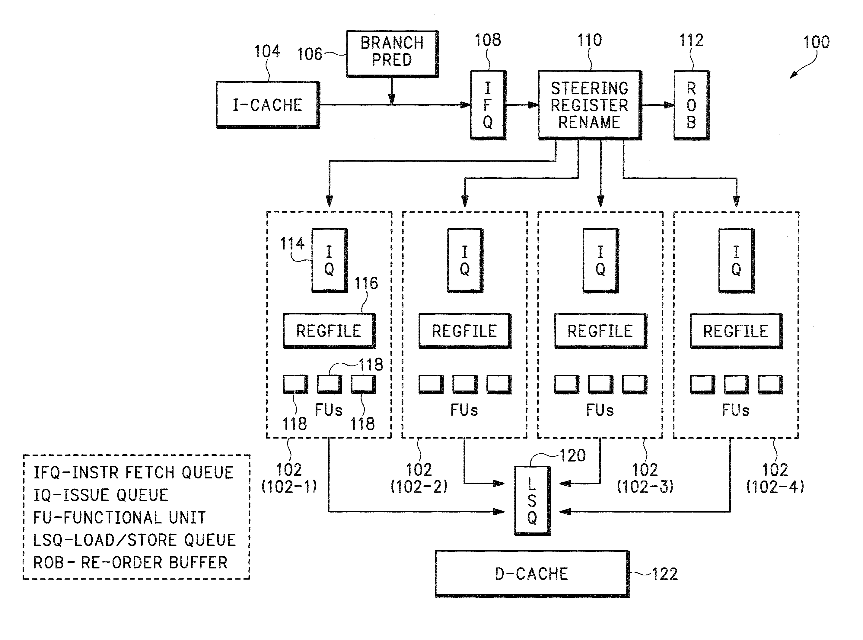
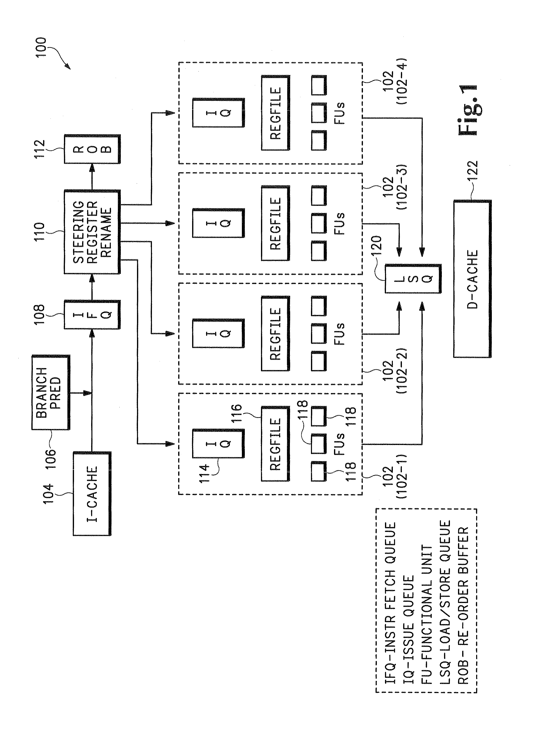
[0033]We start by describing a baseline clustered processor model that has been commonly used in earlier studies. Such a model is shown in FIG. 1 as 100, with four clusters 102 (individually designated 102-1, 102-2, 102-3, and 102-4). Upstream from the four clusters 102 are an instruction cache 104, a branch predictor 106, an instruction fetch cache 108, a steering register rename unit 110, and a reorder buffer 112. Within each cluster 102 are an issue queue 114, a register file 116, and functional units 118. Downstream from the clusters 102 are a load / store queue (LSQ) 120 and a data cache 122.

[0034]The branch predictor 106 and instruction cache 104 are centralized structures, just as in a conventional processor. At the time of register renaming in the steering register rename unit...


PUM


Abstract

In a processor having multiple clusters which operate in parallel, the number of clusters in use can be varied dynamically. At the start of each program phase, the configuration option for an interval is run to determine the optimal configuration, which is used until the next phase change is detected. The optimum instruction interval is determined by starting with a minimum interval and doubling it until a low stability factor is reached.

Description

REFERENCE TO RELATED APPLICATION[0001]The present application claims the benefit of U.S. Provisional Patent Application No. 60 / 577,607, filed Jun. 8, 2004, whose disclosure is hereby incorporated by reference in its entirety into the present application.STATEMENT OF GOVERNMENT INTEREST[0002]The work leading to the present invention was supported in part by NSF grants EIA-0080124, CCR-9811929, CCR-9988361, CCR-0219848, and ECS-0225413; by DARPA / ITO under AFRL contract F29601-00-K-0182; and by the U.S. Department of Energy Office of Inertial Confinement Fusion under Cooperative Agreement No. DE-FC03-92SF19460. The government has certain rights in the invention.FIELD OF THE INVENTION[0003]The present invention is directed to a method for managing the operation of a clustered processor and more specifically to a method for dynamically managing the communication-parallelism trade-off in a clustered processor.[0004]Description of Related Art[0005]The extraction of large amounts of instruc...

Claims


Application Information

Patent Timeline
Patent Type & Authority Patents(United States)
IPC IPC(8): G06F15/80
CPCG06F9/3828G06F9/3836G06F9/3851G06F9/3891G06F15/16G06F9/5061Y02B60/142G06F2209/507Y02B60/167Y02D10/00G06F15/173G06F15/76
Inventor BALASUBRAMONIAN, RAJEEVDWARKADAS, SANDHYAALBONESI, DAVID
Owner UNIVERSITY OF ROCHESTER
Learn More