Casting die filling device

A casting mold and mold-loading technology, applied in the field of mold-loading devices, can solve the problems of manual mold-loading mold sleeve deviation, affecting the quality of casting parts, etc., and achieve the effect of ensuring quality and relative position.

Active Publication Date: 2015-07-22
东至县文元瓷砖加工厂
View PDF5 Cites 5 Cited by
  • Summary
  • Abstract
  • Description
  • Claims
  • Application Information

AI Technical Summary

Problems solved by technology

[0003] The technical problem to be solved by the present invention is to provide a casting mold loading device to solve the problem t

Method used


Image

  • Casting die filling device
  • Casting die filling device

Examples


Embodiment Construction

[0023] In the following, various specific details are set forth in order to provide a thorough understanding of the concepts underlying the described embodiments. However, it is obvious to those skilled in the art that the described embodiments can be practiced without some or all of these specific details. In other cases, well-known processing steps are not specifically described.

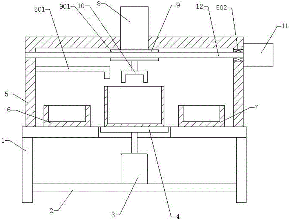
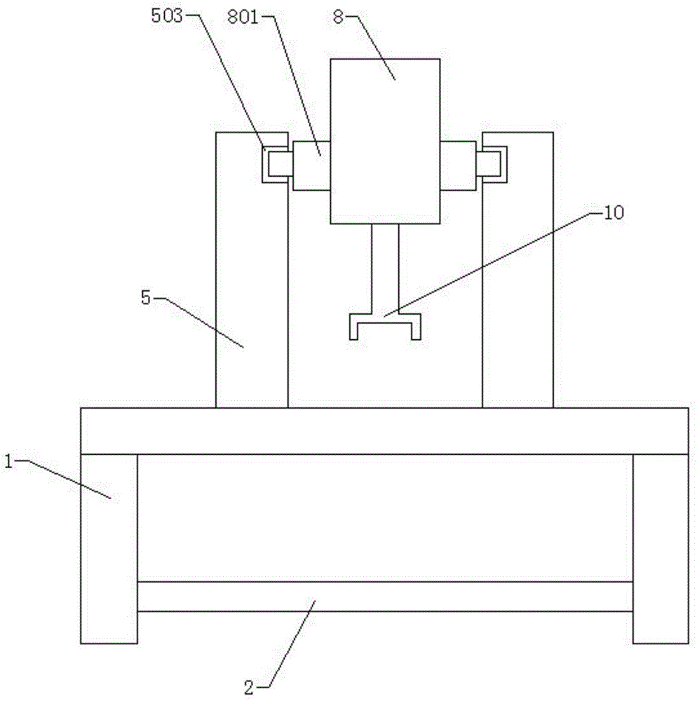
[0024] Such as figure 1 , figure 2 As shown, it includes the workbench 1, the bottom plate 2, the hydraulic cylinder 3, the support plate 4, the bracket 5, the mold sleeve positioning seat 6, the mold core positioning seat 7, the first servo motor 8, the nut seat 9, the clamping jaw 10, and the second The servo motor 11, the screw rod 12, the sand injection pipe 501, the bearing 502, the guide rail 503, the sliding block 801, and the feed nut 901. The bottom plate 2 is located at the center of the bottom of the workbench 1, and the bottom plate 2 is connected to the workbench 1. The hydraulic cyli...


PUM


Abstract

The invention discloses a casting die filling device which comprises a working table, a bottom plate, a hydraulic cylinder, a supporting plate, a bracket, a die sleeve positioning seat, a die core positioning seat, a first servo motor, a nut seat, a clamping jaw, a second servo motor and a screw rod. Compared with the prior art, the casting die filling device replaces a manual die filling manner with a manner of driving by the servo motors to fill the die and ensures relative positions of a die sleeve and a die core so as to ensure quality of a casting part.

Description

Technical field [0001] The invention relates to a mold mounting device, in particular to a casting mold mounting device. Background technique [0002] Casting is a kind of metal thermal processing, which plays an important role in industrial development. Casting is to melt a metal into a liquid, and then inject hydraulic pressure into the mold to obtain the casting. The casting mold is made by placing the wax mold Into the mold cavity, the wax mold core is currently installed manually in the wax mold sleeve, and the relative position of the mold sleeve and the mold core during manual mold installation is controlled by the skill of the worker, which will cause the mold sleeve The deviation from the relative position of the mold core seriously affects the quality of the cast parts. In view of the above-mentioned defects, it is necessary to design a casting mold assembly device. Summary of the invention [0003] The technical problem to be solved by the present invention is to provi...

Claims


Application Information

Patent Timeline
IPC IPC(8): B22C23/00
CPCB22C23/00
Inventor 陈远发蒋亚楠赵银恒李用舟
Owner 东至县文元瓷砖加工厂
Why Eureka
Try Eureka