
Rotating-tube-type multi-tube pulse detonation engine

A detonation engine and pulse detonation technology, applied in mechanical equipment, intermittent injection devices, etc., can solve the problems of large heat load of the detonation tube, inconvenient use, difficulty in ignition coordination and control, etc., to achieve good heat dissipation and ensure relative position, increased reliability, and stability effects

Pending Publication Date: 2018-08-03
张俊良
View PDF0 Cites 2 Cited by
  • Summary
  • Abstract
  • Description
  • Claims
  • Application Information

AI Technical Summary

Problems solved by technology

However, rotary valve detonation engines generally adopt the form of multi-tube installation. The multi-tube structure makes it difficult to coordinate valve control, and there are problems such as coordination and control of air intake and ignition between multiple tubes, and each detonation tube All need to be equipped with intake valves, oil intake valves and corresponding pipelines, resulting in complex structure and inconvenient use of rotary valve detonation engines
At the same time, the traditional pulse detonation engine has a large thermal load on the detonation tube and a low heat dissipation rate, which needs to be improved.

Method used


Image

  • Rotating-tube-type multi-tube pulse detonation engine
  • Rotating-tube-type multi-tube pulse detonation engine
  • Rotating-tube-type multi-tube pulse detonation engine

Examples


Embodiment Construction

[0028] The principles and features of the present invention are described below in conjunction with the accompanying drawings, and the examples given are only used to explain the present invention, and are not intended to limit the scope of the present invention.

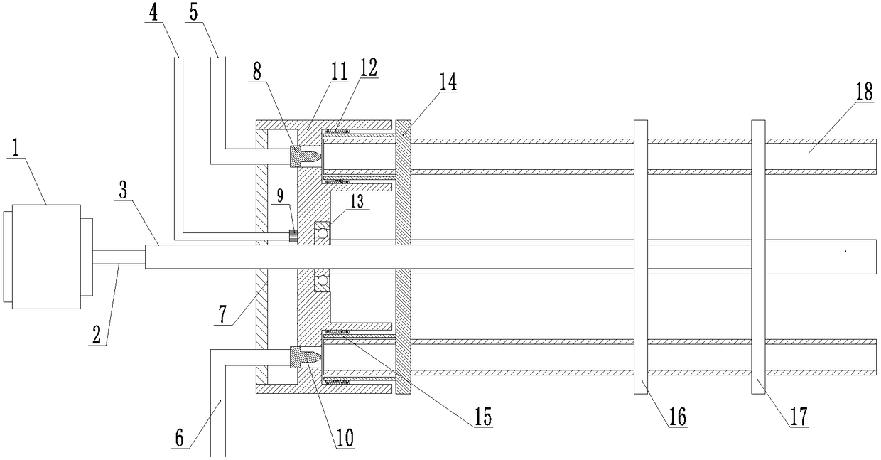
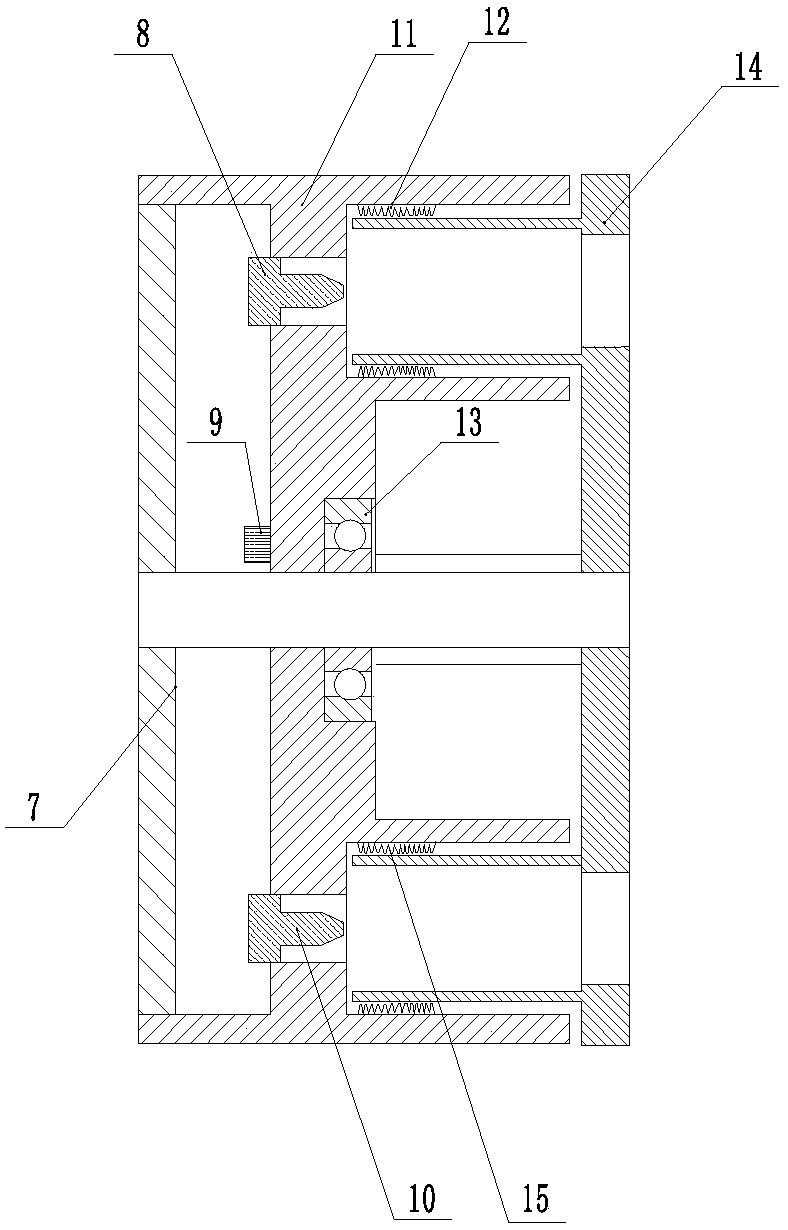
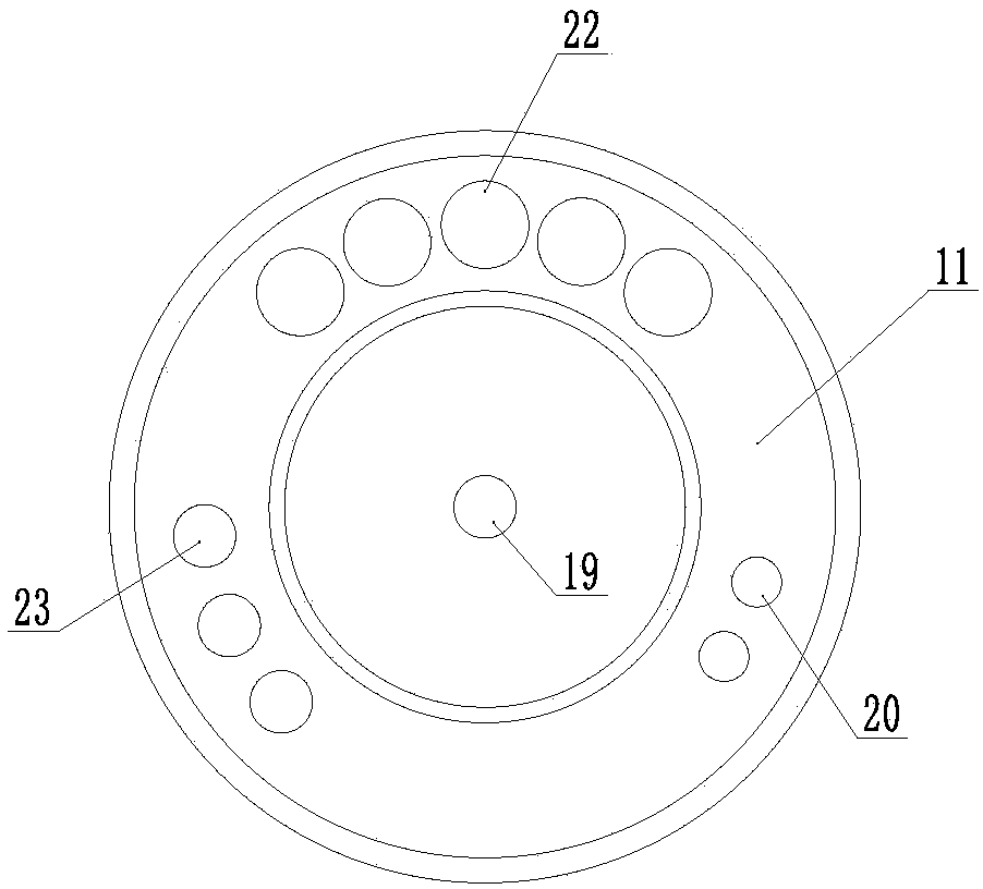
[0029] Such as Figure 1-Figure 5 As shown, a rotary tube type multi-tube pulse detonation engine includes a drive motor 1, a detonation engine main shaft 3 coaxially fixedly connected to the output shaft 2 of the drive motor 1, and at least two detonation tubes 18. The detonation The axis of the tube 18 is arranged parallel to the axis of the detonation engine main shaft 3, the detonation tubes 18 are radially and evenly distributed along the circumference of the detonation engine main shaft 3, and the axis of the detonation tube 18 reaches the detonation engine The spindle axis 3 has the same distance, and also includes a first detonation tube connection plate 16 for connecting the detonation tube 18, and the firs...


PUM


Abstract

The invention relates to the technical field of pulse detonation engines, in particular to a rotating-tube-type multi-tube pulse detonation engine. The rotating-tube-type multi-tube pulse detonation engine comprises a driving motor, a detonation engine spindle coaxially and fixedly connected with an output shaft of the driving motor, and at least two detonation tubes, and the axes of the detonation tubes are arranged to be parallel to the axis of the detonation engine spindle; the rotating-tube-type multi-tube pulse detonation engine further comprises a first detonation tube connecting disc used for being connected with the detonation tubes, first round holes matched with the detonation tubes in diameter are perpendicularly formed in the position, directly facing the axes of the detonationtubes, of the first detonation tube connecting disc in a penetrating mode, and the detonation tubes are fixedly mounted in the first round holes; and the detonation engine spindle drives the detonation tubes to rotate around the axis of the detonation engine spindle through a multi-orifice valve, the end, directly facing the driving motor, of the multi-orifice valve is provided with an explosivemixed gas piping assembly, an air piping assembly and an ignition cable, and the side, back to the driving motor, of the multi-orifice valve is fixedly connected with the ends of the detonation tubes.

Description

technical field [0001] The invention relates to the technical field of pulse detonation engines, in particular to a rotary tube type multi-tube pulse detonation engine. Background technique [0002] Pulse detonation engine is a new concept engine that uses detonation combustion wave to generate thrust. Since the propagation speed of the detonation wave is extremely fast, up to several thousand meters per second, the combustion products have no time to expand during the combustion process, and the detonation process is very close to the constant volume combustion process, so theoretically, its cycle thermal efficiency is significantly higher than that of the constant pressure combustion process. Conventional aero-engines based on the combustion process. In addition, because the detonation process also has a strong supercharging capacity, the detonation engine can eliminate rotating components such as compressors and turbines, so it also has the advantages of simple structure...

Claims


Application Information

Patent Timeline
IPC IPC(8): F02K7/02F02K7/06
CPCF02K7/02F02K7/06
Inventor 张俊良
Owner 张俊良
Learn More