Receiver system

Active Publication Date: 2014-05-01
EM MICROELECTRONIC-MARIN
View PDF2 Cites 29 Cited by
  • Summary
  • Abstract
  • Description
  • Claims
  • Application Information

AI Technical Summary

Benefits of technology

[0016]It is an object of the invention to overcome the drawbacks of the prior art by prop

Problems solved by technology

This results in a saving in the surface area of the printed circuit board and also a saving in terms of costs since the cost of these

Method used


Image

  • Receiver system
  • Receiver system
  • Receiver system

Examples


Embodiment Construction

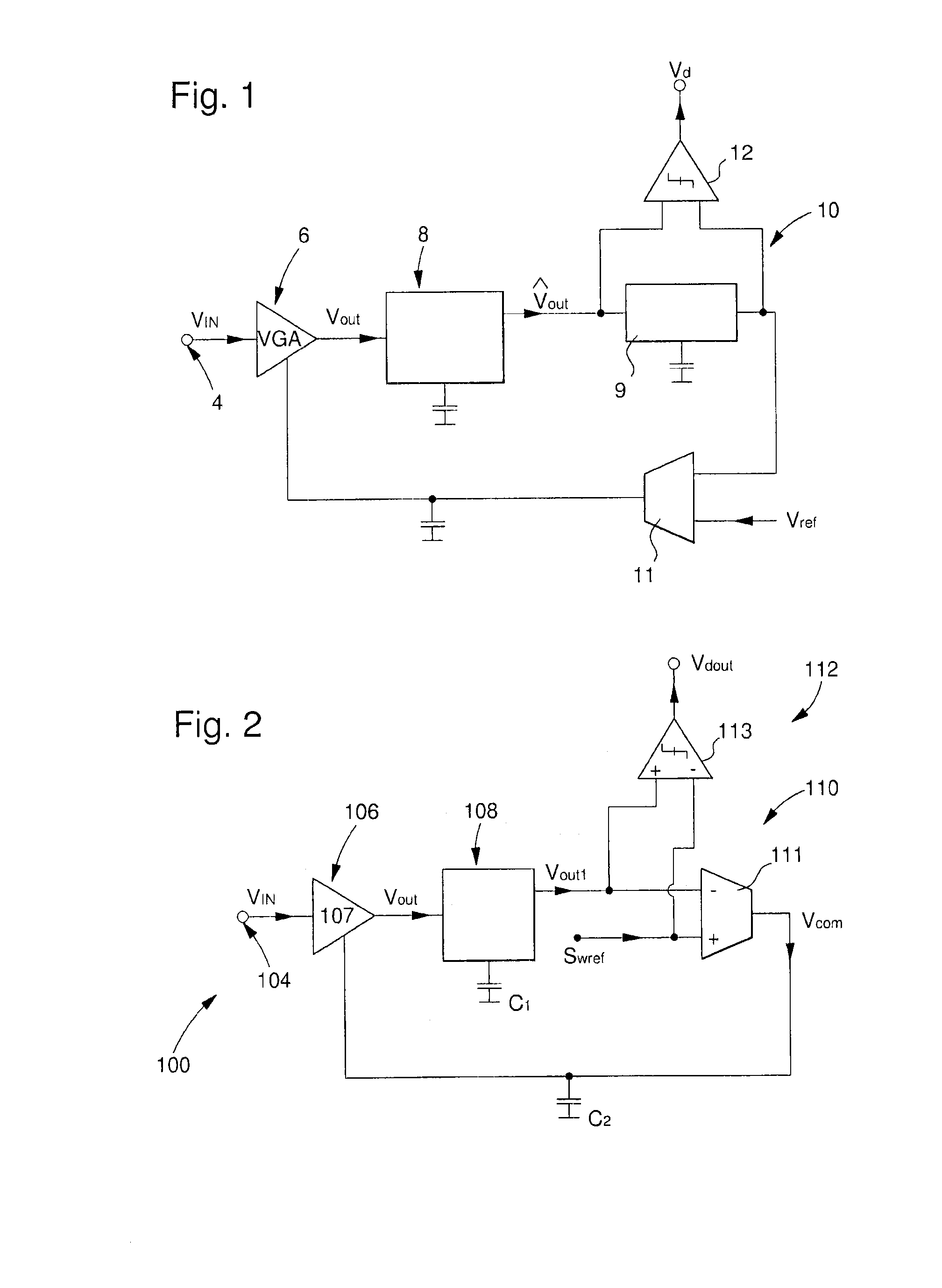
[0034]FIG. 2 shows a receiver circuit or system 100 according to the invention. This receiver circuit 100 includes an input 104 via which a signal is received. This signal Vin is a signal containing data which may equally be a high frequency signal or a low frequency signal. This signal Vin takes the form of an amplitude modulated signal.

[0035]This input 104 is connected to a first input of a first amplifier stage 106. First comparator stage 106 includes a low noise amplifier 107. The purpose of low noise amplifier 107 is to amplify the incoming signal to deliver an amplified input signal Vout.

[0036]The output of first amplifier 106 is connected to an envelope detector stage 108. Envelope detector stage 108 is used to demodulate the amplified input signal Vout which is the amplified incoming signal Vin, i.e. to deliver a detected signal Vout1 matching the contours of the amplified incoming signal. Envelope detector stage 108 is also used for extracting data concerning the amplitude ...


PUM


Abstract

The present invention concerns a receiver circuit including an input terminal through which an input signal is received, said receiver circuit further including:
    • a first amplifier stage connected via its input to the input terminal of said receiver circuit;
    • an envelope detector stage for detecting the incoming signal maxima to recover the signal envelope, said detector stage being connected to the output of the first stage.

Description

[0001]This application claims priority from European Patent application No. EP12190222.5 filed Oct. 26, 2012, the entire disclosure of which is incorporated herein by reference.[0002]The invention concerns the field of receiver systems and / or circuits including an input terminal through which an input signal is received, said receiver circuit further including:[0003]a first amplifier stage connected via its input to the input terminal of said receiver circuit;[0004]an envelope detector stage for detecting the incoming signal maxima to recover the signal envelope, said detector stage being connected to the output of the first stage.BACKGROUND OF THE INVENTION[0005]It is known that devices such as mobile telephones or satellites or various portable objects are provided with transceiver circuits including a transmission loop used to transmit a signal and a receiving loop used to receive a signal. Some devices such as radio tuners are only provided with an electronic receiver circuit, i...

Claims


Application Information

Patent Timeline
IPC IPC(8): H04B1/16
CPCH03D1/10H03G3/3052H04B1/16H03D1/18H03K5/007H03G3/30H03K9/00H03K9/02H04L27/08H03D1/06H03D2200/0047H04L27/06
Inventor TAJALLI, ARMIN
Owner EM MICROELECTRONIC-MARIN
Why Eureka
Try Eureka