Liquid container, ink jet cartridge and ink jet printing apparatus

a liquid container and ink jet technology, applied in printing and other directions, can solve the problems of increasing the size and cost of the printing apparatus and a complication of the structure, increasing the size and/or weight of the ink jet cartridge, and increasing the weight of the entire carriag

Inactive Publication Date: 2005-01-11
CANON KK
View PDF17 Cites 30 Cited by
  • Summary
  • Abstract
  • Description
  • Claims
  • Application Information

AI Technical Summary

Benefits of technology

The present invention provides a liquid container, an ink jet cartridge, and an ink jet printing apparatus which can solve one or more of the above described problems.
According to the present invention, it is possible to inexpensively construct a liquid container for containing the liquid such as ink as well as an ink jet cartridge and a printing apparatus both provided with the liquid container, and to improve the stability and reliability of supply of the liquid to the container.

Problems solved by technology

However, according to such a tube supply method, the movement of the cartridge affects the flow of the ink in the tube in the direction in which the carriage moves, so that the ink may be ejected unstably from the print head.
Further, the tube supply method has various problems associated with the need for a tube long enough to allow the carriage to be reciprocated.
Thus, the tube does not only have a smaller added value but also results in an increase in the size and cost of the printing apparatus and a complication of the structure, or the like.
An increase in the size and / or weight of the ink jet cartridge increases the weight of the entire carriage, on which the ink jet cartridge is installed.
This may increase the size of a motor that drives the carriage, driving power, and the size and weight of the entire printing apparatus.
Accordingly, the capacity of the ink tank installed on the carriage is limited to an extremely small value.
However, the frequent replacement of the ink tank does not satisfy demands for user-friendly apparatuses and environment preservation.
Furthermore, it is unnecessary to have such a tube as is required for the above described tube supply method.
However, a mechanism for this method is very complicated, delicate, and expensive.
However, the total amount of waste ink sucked from the sub-tank during each pit-in operation is not negligible.
Also, tight design restrictions are imposed on, in particular, small-sized ink jet printing apparatuses.
Thus, it is unnecessary to control the sucking of air.
Such demands for colored and more inexpensive printing apparatuses pose various problems in actually applying a configuration as shown in FIGS. 16 and 17.
Further, in this case, if providing relatively expensive gas liquid separation member for each of the ink absorbing members, the number of sub-tank unit components and the number of assembly steps increase.
Thus, it is difficult to reduce the costs of the printing apparatus.
In this case, if the ink remains on the gas liquid separation members, the characteristic (suction characteristic) of ventilation through the gas liquid separation members is deteriorated.
Thus, it is difficult to stabilize the supply of ink to the ink absorbing members in the sub-tanks and maintain reliability.
However, even this configuration fails to solve the problem that ink remains on the gas liquid separation members as described above.
However, in this case, the shape of the ink absorbing members becomes complicated, thus increasing the costs of the sub-tank unit and thus the entire printing apparatus.
Furthermore, the gas liquid separation members may interfere with the ink absorbing members and vice versa.
This may cause the leakage of ink or internal air.

Method used


Image

  • Liquid container, ink jet cartridge and ink jet printing apparatus
  • Liquid container, ink jet cartridge and ink jet printing apparatus
  • Liquid container, ink jet cartridge and ink jet printing apparatus

Examples


first embodiment

A second embodiment of a liquid container according to the present invention will be described below with reference to FIGS. 6 to 8. The same elements as those described with reference to the first embodiment are referred to same reference numerals and same description will be omitted.

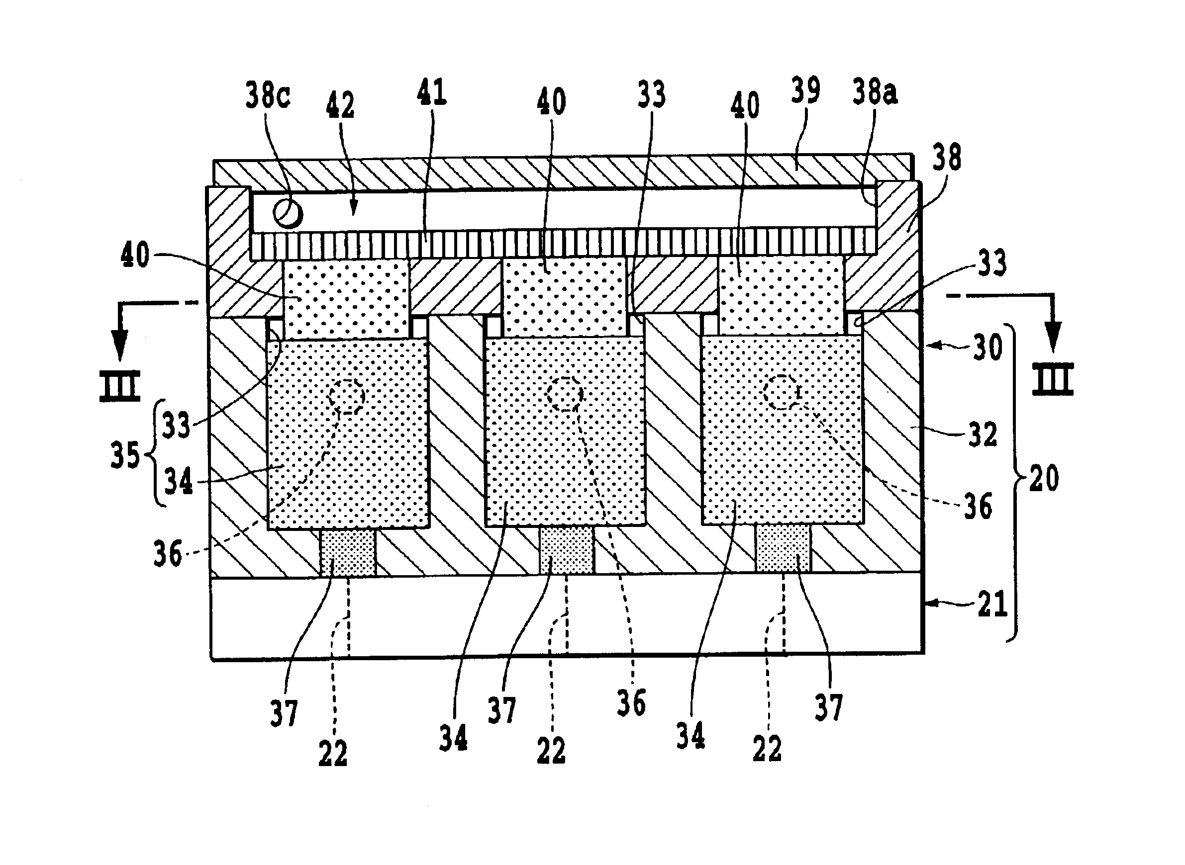
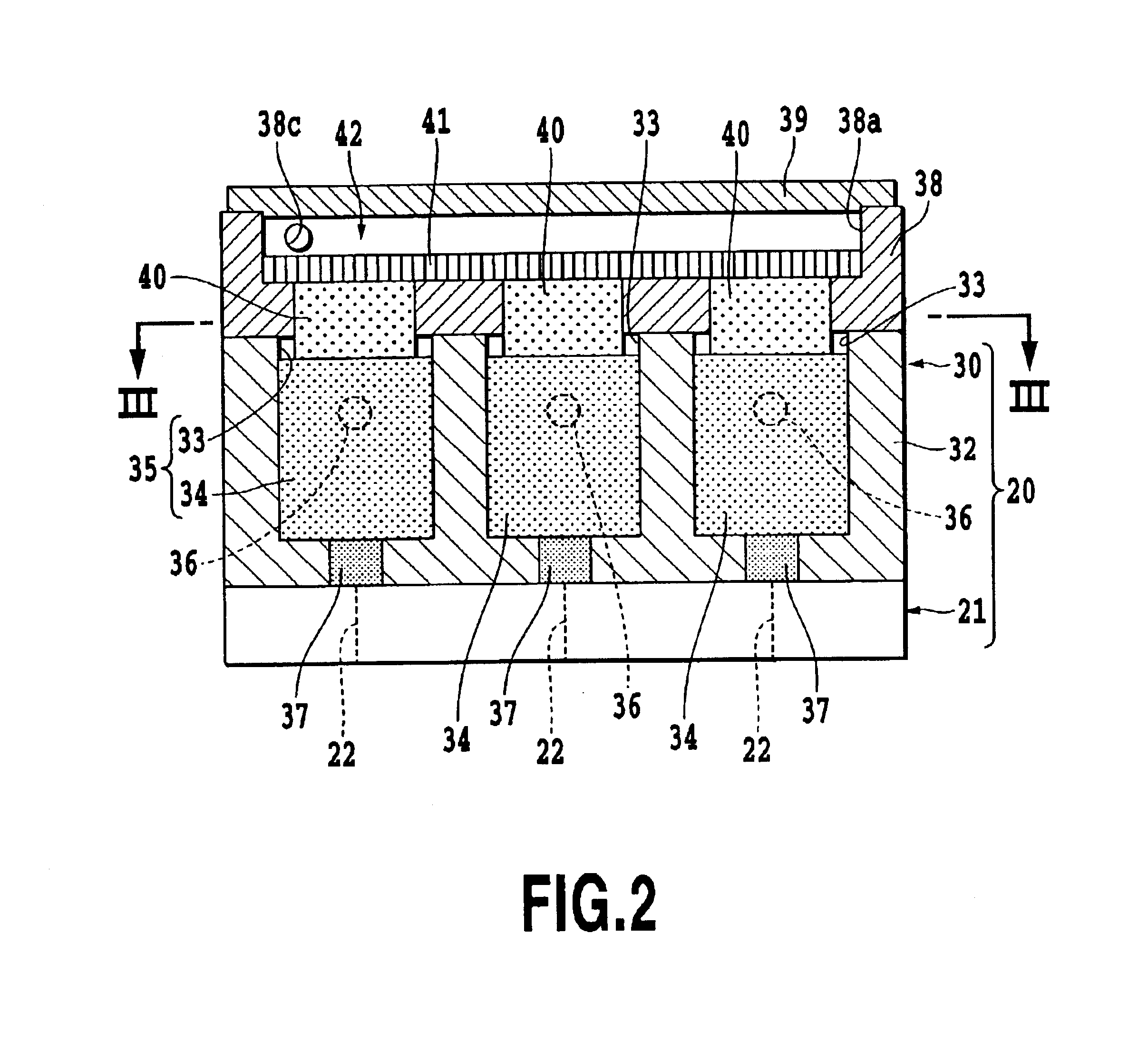
A sub-tank unit 30A of FIG. 6 has a configuration basically similar to that of the above described sub-tank unit 30 but includes capillary members 40A different from the capillary members 40 of the sub-tank unit 30. As shown in FIGS. 6 and 7, each of the capillary members 40A has a penetration hole 43 extending from one end surface (end surface opposing to the gas liquid separation member 41) to the other end surface (end surface opposing to the ink absorbing member 34) of the capillary member 40A. The hole 43 includes a central portion 44 having a generally rectangular cross section and a plurality of narrowed portions (slit) 45 extending from an edge of the central portion 44 longitudinally outward i...

second embodiment

FIGS. 9 to 14 show variations of the capillary member according to the As capillary members 40B to 40G shown in these drawings, the form of the capillary member may be optionally selected depending on the size or shape of the container main body 32, the characteristics of the ink, or the like.

The capillary members 40B and 40C shown in FIGS. 9 and 10 respectively include short narrowed portions 45 which are formed to extend in a direction perpendicular to the longitudinal direction of the cross section of the capillary members 40B and 40C. The capillary member 40D shown in FIG. 11 corresponds to the integration of three capillary members 40A described above. A sub-tank unit using the capillary member 40D requires only one chamber for accommodating the capillary member 40D. The one chamber and the capillary member 40D serve as a plurality of ink storages. The capillary members 40E to 40G shown in FIGS. 12 to 14 respectively include an outer frame portion 46 and comb-like or annular e...


PUM


Abstract

A sub-tank unit of an ink jet cartridge can contain ink for image printing therein. The sub-tank unit includes a container main body having a ink storage for storing the ink, a ventilation path enabling the liquid storage and the outside of the container main body to communicate with each other, a gas liquid separation member disposed to communicate with the ventilation path, and a capillary member disposed between the ink storage and the gas liquid separation member.

Description

This application claims priority from Japanese Patent Application No. 2002-046709 filed Feb. 22, 2002, which is incorporated hereinto by reference.BACKGROUND OF THE INVENTION1. Field of the InventionThe present invention relates to a liquid container, an ink jet cartridge and an ink jet printing apparatus.2. Related Background ArtFor ink jet printing apparatuses, a large number of means for supplying ink to an ink jet print head have been proposed and in practical use. The most traditional ink supply method for ink jet printing apparatuses is a tube supply method of supplying ink from an ink tank in the printing apparatus to a print head on a cartridge via a tube. However, according to such a tube supply method, the movement of the cartridge affects the flow of the ink in the tube in the direction in which the carriage moves, so that the ink may be ejected unstably from the print head. Thus, oscillation of the ink in the tube must be suppressed in order to increase printing speed.Fu...

Claims


Application Information

Patent Timeline
Patent Type & Authority Patents(United States)
IPC IPC(8): B41J2/175
CPCB41J2/17513
Inventor TANIGUCHI, SUGURUTSUJIMOTO, AKIRAUJITA, TOSHIHIKOKUDO, KIYOMITSU
Owner CANON KK
Why Eureka
Try Eureka