
Expansible Intervertebral Implant

an intervertebral implant and expansion technology, applied in the field ofvertebral implants, can solve the problems of high patient invasiveness, complex prior art implants, and large volume of prior art implants, and achieve the effect of facilitating and accelerating the implantation of intervertebral implants, reducing the invasiveness of implantation and the cost of necessary instruments

Active Publication Date: 2018-05-10
LDR MEDICAL
View PDF3 Cites 27 Cited by
  • Summary
  • Abstract
  • Description
  • Claims
  • Application Information

AI Technical Summary

Benefits of technology

This patent proposes an intervertebral implant that addresses some of the drawbacks of prior art designs by being limited in invasiveness and having improved stability and reliability. The implant can be expanded easily for the surgeon and can optionally impose lordosis. The patent also introduces instrumentation to facilitate and accelerate the implantation process, improving stability and reliability while reducing the invasiveness and cost of the necessary instruments.

Problems solved by technology

A frequent problem in the field of vertebral implants and especially of corpectomy cages or intervertebral cages relates to the ability to maximize the stability of such implants so as to cover a volume which most closely approaches the volume occupied by the affected vertebral disc.
Implants of the prior art therefore generally have substantial volume, which makes their implantation highly invasive for the patient.
Nevertheless, this type of expansible cages has a certain number of drawbacks.
Moreover, the prior art implants are complex, deploy only in a single direction (in height, or in lordosis, or in surface area) and without stabilizing elements intrinsic to said implants.
This imposes a difficulty for the surgeon in complying with a specific lordosis.
In fact, this type of cage does not allow a considerable deployment amplitude and the expansion in height may therefore be insufficient for effectively restoring the height and the desired intervertebral lordosis.
The expansion in surface area may be insufficient to provide support for the implant on the peripheral zones of the vertebral endplate, which is generally stronger, because the implant will remain positioned over the more central zones, causing a greater risk of collapse of the implant into the vertebral body.

Method used


Image

  • Expansible Intervertebral Implant
  • Expansible Intervertebral Implant
  • Expansible Intervertebral Implant

Examples


Embodiment Construction

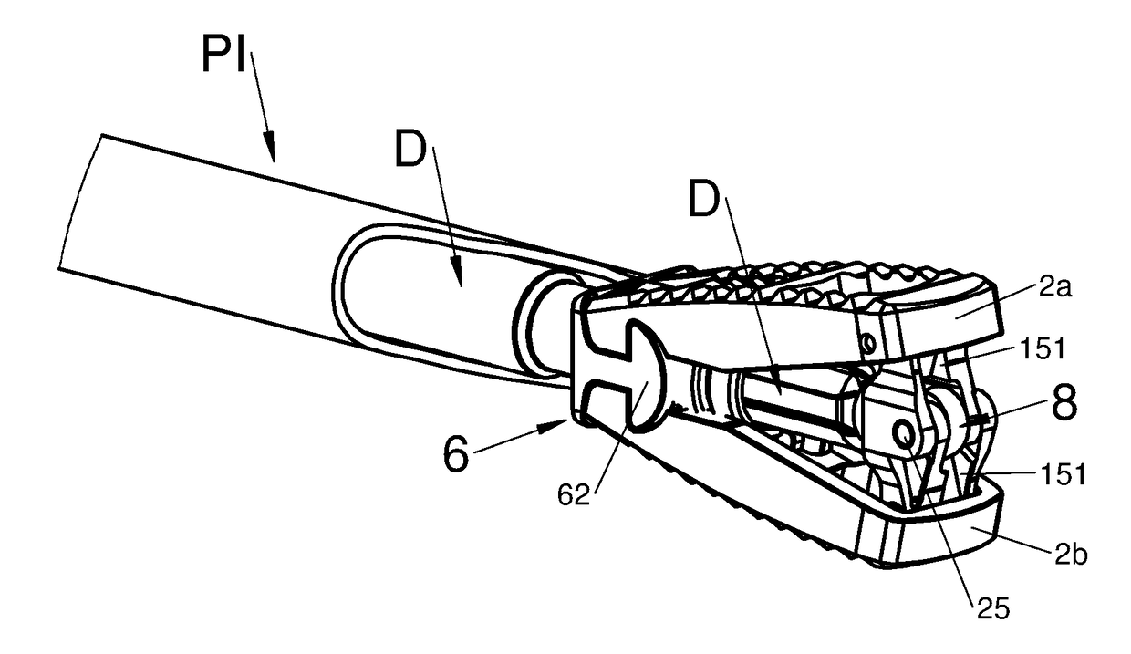
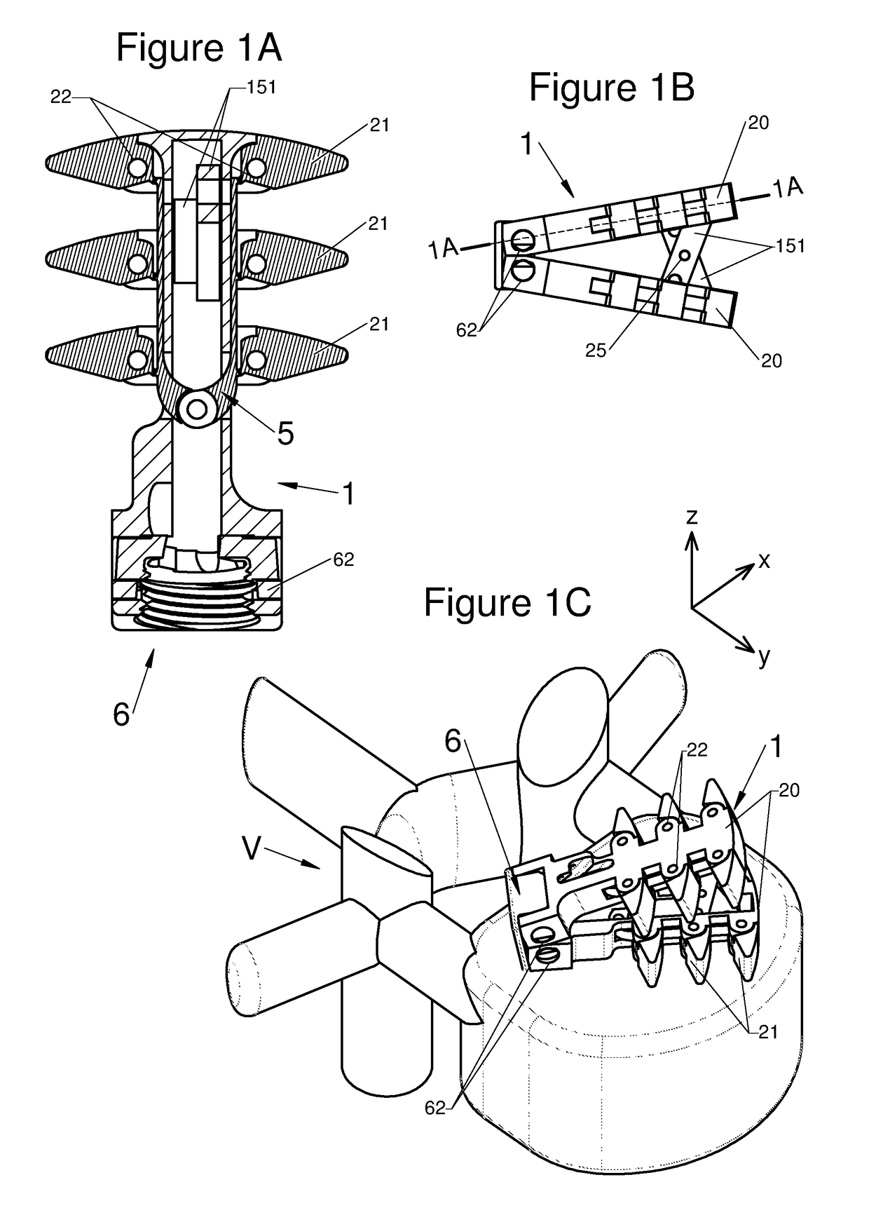
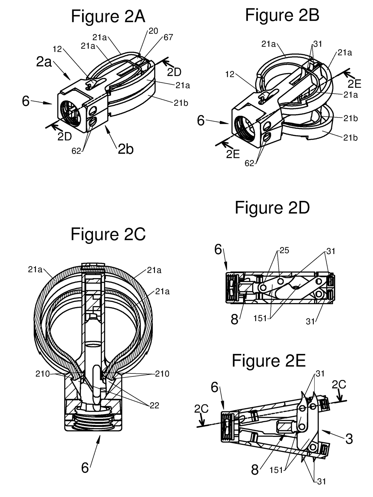
[0063]The present disclosure relates to a vertebral implant, adapted for use in the spine and intended to be implanted in general in a vertebral segment composed of at least two vertebrae. This implant is provided to be deployed horizontally, vertically and laterally by way of various elements participating in said deployment or expansion of said implant.

[0064]These various elements are different from one another, but they have the advantage of all participating in the horizontal, vertical and / or lateral expansion of the implant. This makes it possible to group these elements according to the term “expansion means” and the different technical features of each expansion means will be detailed below. Indeed, this implant could be an implant of “intervertebral” type implanted between two adjacent vertebrae or an implant of “corpectomy” type implanted on a segment which may extend beyond a single intervertebral space, or even over several bodies and / or vertebral spaces. In fact, various...


PUM


Abstract

Various embodiments of an intervertebral implant comprise a body extending longitudinally along a primary axis, a baseplate, a plurality of elongated arms having a vertebral support surface, the arms being articulated such that the implant has a folded-back position in which the arms are close to each other, and a deployed position in which the arms are moved away from each other, and expansion means between the folded-back and deployed positions, comprising at least two branches pivotably mounted relative to each other and attached to the elongated arms by guide means such that translation of the expansion means parallel to the primary axis causes pivoting of the branches and moves the arms away from each other.

Description

CROSS-REFERENCE TO RELATED APPLICATIONS[0001]This application claims priority under 35 U.S.C. § 119 to French Patent Application No. FR1660472 filed in FRANCE on Oct. 27, 2016, which is incorporated herein by reference.BACKGROUND[0002]The present disclosure relates to the field of vertebral implants and in general to the field of implants intended to be implanted between two vertebrae to at least partially supplant an intervertebral disc. The present disclosure relates more particularly to an expansible intervertebral implant, of corpectomy cage or intersomatic cage type.[0003]Intervertebral implants are implanted between two adjacent vertebrae to allow insertion and growth of bone tissue grafts (or substitute) in the disc space to create arthrodesis (fusion of two vertebrae). The intervertebral space, after the cage is placed, is generally filled with autologous cancellous bone or adapted bone substitutes.[0004]Various arthrodesis techniques are known from the prior art, based on v...

Claims


Application Information

Patent Timeline
IPC IPC(8): A61F2/44A61F2/30A61F2/46
CPCA61F2/447A61F2/30771A61F2/4611A61F2002/30362A61F2002/30429A61F2002/30471A61F2002/30579A61F2002/30553A61F2002/30828A61F2002/30904A61F2002/4629A61F2002/4475A61F2002/4624A61F2002/4687A61F2002/4602A61F2/4601A61F2002/4627A61F2/4455A61F2002/30538A61F2002/30556A61F2/4603A61F2002/30593A61F2/4261A61F2/4609
Inventor BERNARD, PIERRECHATAIGNER, HERVECHEBUHAR, CRAIGKIRGIS, ALEXANDERSHERBAN, ROSSLEQUETTE, SAMUELBOUGERE, EMMANUELFRESNEAU, AYMERICROCHE, NICOLAS
Owner LDR MEDICAL
Learn More