Four-connecting-rod lifting system applied to roll gang

A technology of conveying roller table and four-bar linkage, which is applied in the field of lifting system, can solve the problems of tilting of lifting roller table and stuck motion system, and achieves the effect of simple assembly and guaranteed feasibility.

Inactive Publication Date: 2015-07-22
CHINA TRIUMPH INT ENG
View PDF9 Cites 1 Cited by
  • Summary
  • Abstract
  • Description
  • Claims
  • Application Information

AI Technical Summary

Problems solved by technology

In addition, when the area of ​​the lifting roller table is relatively large, the lifting roller table needs to apply loads from multiple directions at the same time to make it rise, but if the force is not uniform in each direction, it will directly cause the lifting roller table to tilt, and even the motion system will be stuck.

Method used


Image

  • Four-connecting-rod lifting system applied to roll gang
  • Four-connecting-rod lifting system applied to roll gang

Examples


Embodiment Construction

[0018] The invention will be described in more detail below with reference to the accompanying drawings of specific embodiments of the invention. However, this invention may be embodied in many different forms and should not be construed as limited to the embodiments set forth herein. Rather, these embodiments are provided so that this disclosure will be thorough and complete, and will fully convey the scope of the invention to those skilled in the art.

[0019] A four-link lifting system applied to a conveying roller table according to an embodiment of the present invention will now be described in detail with reference to the accompanying drawings.

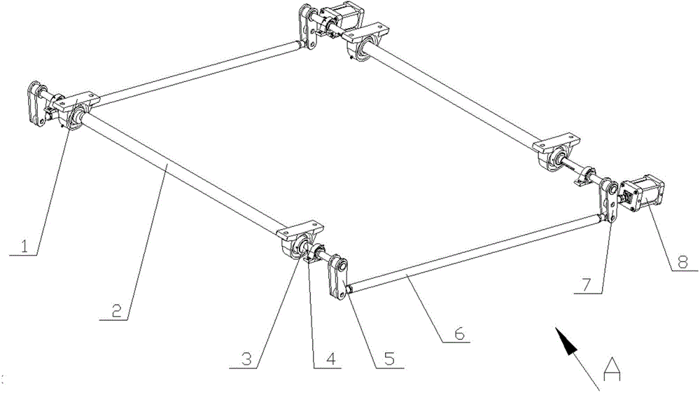
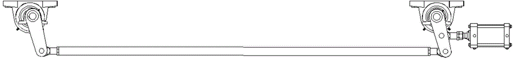
[0020] The four-link lifting system according to the present invention is composed of two sets of shafts, and the structures of the two sets of shafts are the same. For the sake of brevity, only refer to figure 1 and 2 Describe one of the groups.

[0021] Such as figure 1 and 2 As shown, the first bearing 1 is assembled wit...


PUM


Abstract

The invention discloses a four-connecting-rod lifting system applied to a roll gang. A four-connecting-rod system is formed by shafts and connecting rods. Eccentric wheels installed on the shafts play a role in enabling components needing to move to ascend and descend. According to the four-connecting-rod lifting system applied to the roll gang, the ascending and descending functions of the movable components are achieved through the eccentric wheels, the inner diameter parts and the outer diameter parts of the eccentric wheels are assembled with bearing blocks and the shafts, and meanwhile clamping points do not occur in the ascending and descending process. Assembling is easy, the connecting function of two components can be achieved, and meanwhile the movable components can ascend and descend in a flatness mode. Moving feasibility of the system can be guaranteed through the main shafts provided with the eccentric wheels, and meanwhile the load of the movable components can be borne.

Description

technical field [0001] The invention relates to a lifting system which can be used for a 90° turning device in a conveying roller table, in particular to a four-link lifting system applied to a conveying roller table. Background technique [0002] In the conveying roller table, it is often necessary to reverse the direction of the roller table due to site restrictions or classification needs. The principle is: when a group of fixed roller tables and a group of lifting roller tables form the steering equipment, due to problems such as structural layout, simplicity and beauty, it is necessary to share a set of supporting structures for the lifting roller tables and the fixed roller tables. In addition, when the area of ​​the lifting roller table is relatively large, the lifting roller table needs to apply loads from multiple directions at the same time to make it rise. However, if the force applied in each direction is uneven, it will directly cause the lifting roller table to...

Claims


Application Information

Patent Timeline
Patent Type & Authority Applications(China)
IPC IPC(8): B65G47/53
Inventor 谷天奇魏晓俊官敏惠建秋王海林杨黎虹蒋鸿于涛赵永
Owner CHINA TRIUMPH INT ENG
Why Eureka
Try Eureka