Connecting rod lubrication oil delivery structure of diesel engine

A lubricating oil and diesel engine technology, applied in the direction of engine lubrication, pressure lubricant, engine cooling, etc., can solve the problems of discounted cooling effect, difficulty in piston, and obtaining cooling effect, so as to improve the ratio of lubricating oil delivery and strengthen the cooling effect , the effect of strengthening the cooling effect

Active Publication Date: 2015-07-22
GUANGXI YUCHAI MASCH CO LTD
View PDF8 Cites 0 Cited by
  • Summary
  • Abstract
  • Description
  • Claims
  • Application Information

AI Technical Summary

Problems solved by technology

[0003] However, in the above method of forced cooling through the connecting rod to the inner cavity of the piston, due to space and angle constraints, the oil inlet of the internal cooling oil passage located in the inner cavity of the piston cannot receive 100% lubricating oil during the entire stroke of the piston. , which makes it difficult for the piston to obtain a consistent cooling effect during a working cycle of the piston
Therefore, the application scope of the connecting rod oiling method is limited, and the power-up and explosion pressure level of the diesel engine using the connecting rod oiling method are limited.
In order to ensure the cooling effect of the piston, the process of the connecting rod delivering lubricating oil to the piston is mainly concentrated near the top dead center, that is, it presents a symmetrical distribution before and after the top dead center, and the cooling demand of the piston after the top dead center is much higher than that before the top dead center, which is symmetrically distributed The oil delivery method greatly reduces the cooling effect

Method used


Image

  • Connecting rod lubrication oil delivery structure of diesel engine
  • Connecting rod lubrication oil delivery structure of diesel engine

Examples


Embodiment Construction

[0017] The specific embodiments of the present invention will be described in detail below in conjunction with the accompanying drawings, but it should be understood that the protection scope of the present invention is not limited by the specific embodiments.

[0018] Unless expressly stated otherwise, throughout the specification and claims, the term "comprise" or variations thereof such as "includes" or "includes" and the like will be understood to include the stated elements or constituents, and not Other elements or other components are not excluded.

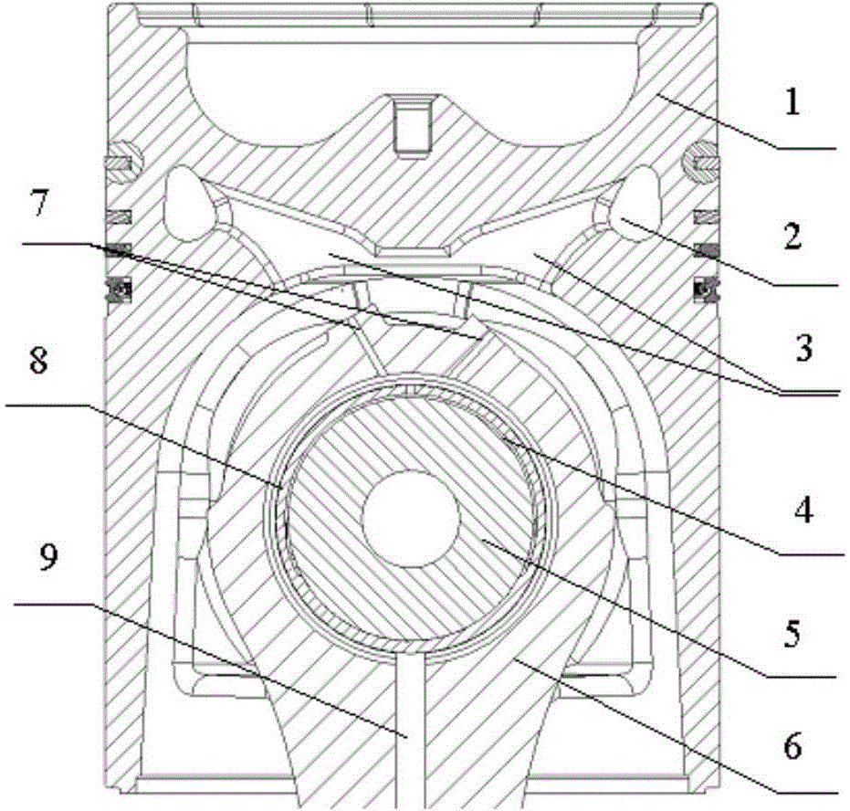
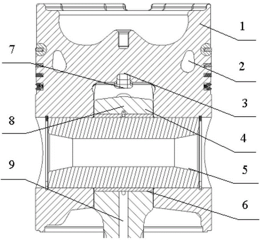
[0019] Such as figure 1 and figure 2 As shown, according to a connecting rod lubricating oil delivery structure of a diesel engine according to a specific embodiment of the present invention, the lubricating oil cools the piston 1 of the diesel engine, the inside of the piston 1 has an internal cooling oil passage 2, and the top The wall is symmetrically provided with two oil inlets 3 communicating with the internal cool...


PUM


Abstract

The invention discloses a connecting rod lubrication oil delivery structure of a diesel engine. A piston of the diesel engine is cooled by using lubrication oil and is provided with an inner oil cooling channel in the inside, two oil inlets communicated with the inner oil cooling channel are symmetrically formed in the top wall of the inner cavity of the piston, the piston is hinged to the small end of a connecting rod together, the small end of the connecting rod is located in the inner cavity of the piston, two asymmetrical oil feeding spray holes are formed in the top of the small end of the connecting rod, and at least one oil feeding spray hole is aligned to the oil inlets in all strokes of the piston behind an upper stop point. By the adoption of the connecting rod lubrication oil delivery structure, the cooling effect on the piston behind the upper stop point is enhanced by improving the conveying proportion of lubrication oil in front of the upper stop point to lubrication oil in back of the upper stop point, so that the piston meets the higher load requirement.

Description

technical field [0001] The invention relates to the field of diesel engine lubrication, in particular to a connecting rod lubricating oil delivery structure of a diesel engine. Background technique [0002] With the continuous improvement of modern diesel engines, in order to ensure the reliable and safe operation of diesel engines, pistons usually use internal cooling oil passages for enhanced cooling, and the lubricating oil required for piston internal cooling oil passages of medium and heavy-duty diesel engines is usually delivered to the piston through connecting rods. cavity way. Specifically, the machine body is provided with a lubricating oil passage leading to the main bearing cap, the main bearing bush is provided with a certain oil groove, and the main journal of the crankshaft and the connecting rod neck are provided with a communicating lubricating oil passage, so as to transport the lubricating oil transferred from the main bearing seat to the connecting rod ne...

Claims


Application Information

Patent Timeline
IPC IPC(8): F01P3/08F01M1/06
Inventor 张锦陈彪苏怀林沈捷
Owner GUANGXI YUCHAI MASCH CO LTD
Why Eureka
Try Eureka