
A Method for Identifying Gas Reservoirs Using Wavelet Phase Features

A feature recognition and wavelet technology, applied in the field of identifying gas reservoirs using wavelet phase features, can solve problems such as difficulty in obtaining wavelet phase information, time resolution limitation methods, and limited phase applications, so as to improve the ability to describe, time high resolution effects

Active Publication Date: 2017-04-26
CHINA NAT OFFSHORE OIL CORP +1
View PDF4 Cites 0 Cited by
  • Summary
  • Abstract
  • Description
  • Claims
  • Application Information

AI Technical Summary

Problems solved by technology

However, these methods have two shortcomings: first, the low time resolution limits the application of the method to characterize thin layers; second, it is difficult to obtain wavelet phase information, which limits the application of phase in hydrocarbon detection

Method used


Image

  • A Method for Identifying Gas Reservoirs Using Wavelet Phase Features
  • A Method for Identifying Gas Reservoirs Using Wavelet Phase Features
  • A Method for Identifying Gas Reservoirs Using Wavelet Phase Features

Examples


Embodiment 1

[0046] Example 1: Fitting Data Example

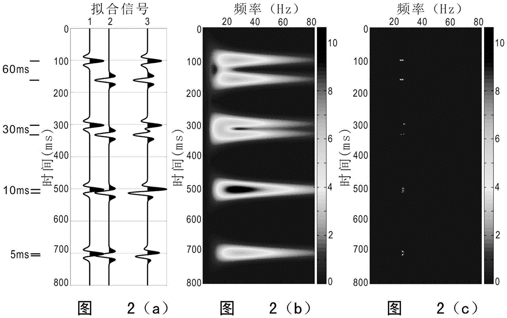
[0047] Such as figure 2 As shown, this embodiment is an example of the ability of the method of the present invention to resolve thin layers. figure 2 (a) is a fitting signal composed of Ricker wavelet pairs with different time intervals, which is used to characterize the top and bottom reflections of formations with different thicknesses. figure 2 (b) is the time-frequency energy spectrum obtained by the CWT method. When the formation is thick (60ms interval), the CWT method can distinguish the top and bottom reflections of the formation; as the formation thickness becomes thinner ( figure 2 (c) is the time-frequency energy spectrum obtained by the complex spectral decomposition method. It can be seen that the time resolution of the invented complex spectral decomposition method is very high.

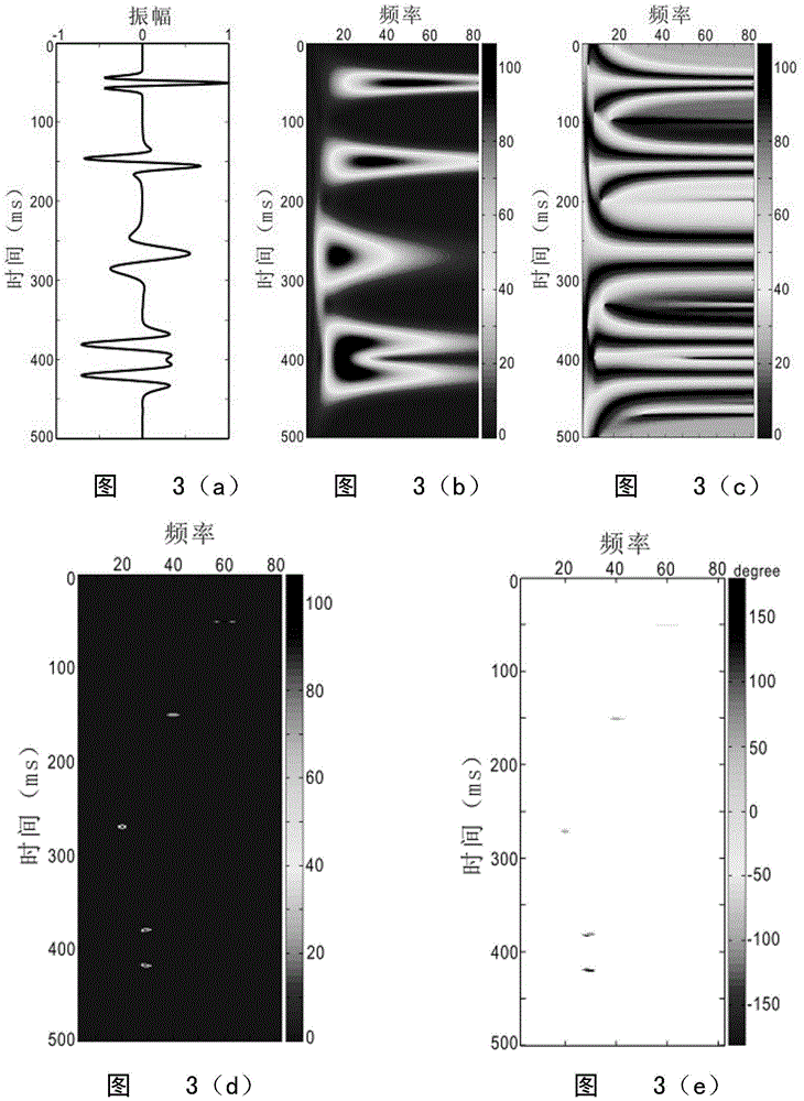
[0048] Such as image 3 Shown is an example of a fitted seismic signal composed of Ricker wavelets of different frequencies and phases. ...

Embodiment 2

[0050] Example 2: Actual Data Example

[0051] Such as Figure 5(a) ~ Figure 5(d) As shown, this embodiment is an example of actual data. Fig. 5(a) is the seismic section of the target area through the exploratory well, and the logging curve projected on the section is the water saturation curve. The positions of gas and water layers revealed by exploratory wells and geological interpretation are indicated in the figure. Figure 5(b) is the frequency anomaly profile used for hydrocarbon detection obtained by the CWT method, the time resolution is lower than the seismic resolution, and it cannot accurately describe thin layers; Figure 5(c) is the complex spectrum proposed in this paper The frequency anomaly profile obtained by the decomposition method has a high time resolution and is consistent with the formation position revealed by the logging. The gas-bearing reservoir has a response in the frequency anomaly profile, but the water layer also has a response in the frequenc...


PUM


Abstract

The invention relates to a method for recognizing gas reservoirs by utilizing wavelet phase features. The method includes the steps: building a plural convolution model; calculating according to the plural convolution model to acquire a time frequency energy spectrum and a time frequency phase spectrum; selecting reservoir effective seismic response starting main frames f1 and f2, and stacking complex reflection coefficient within a frequency range from f1 to f2 along the frequency direction to acquire a reservoir-related complex reflection coefficient spectrum; performing modulus square and anti-tangent operation on the reservoir-related complex reflection coefficient to respectively acquire a frequency abnormality spectrum and a phase abnormality spectrum; utilizing the frequency abnormality spectrum and the phase abnormality spectrum for gas reservoir recognition. The method can be used for detecting gas reservoirs with high attenuation features, capability of describing thin reservoirs can be improved effectively, and solution multiplicity of explaining can be lowered. The method can be widely applied in the process of oil-gas exploration.

Description

technical field [0001] The invention relates to a seismic hydrocarbon detection method, in particular to a method for identifying gas reservoirs using wavelet phase features applied in the oil exploration process. Background technique [0002] Petrophysical simulation and exploration practice show that when waves propagate in fluid-bearing media, they will be affected by media attenuation, and high frequencies are more likely to be attenuated than lower frequencies. Therefore, existing technologies often use low-frequency anomaly profiles for hydrocarbon prediction. However, in actual exploration, this method often fails, because the water layer also attenuates the seismic waves and produces a spectral response similar to that of hydrocarbon reservoirs. In fact, attenuation and dispersion not only change the frequency of the wavelet, but also change the phase of the wavelet, but the phase feature has not been utilized. The main reason is that the current understanding of th...

Claims


Application Information

Patent Timeline
Patent Type & Authority Patents(China)
IPC IPC(8): G01V1/30
Inventor 刘春成韩利张益明仝中飞叶云飞牛聪黄饶杨小椿
Owner CHINA NAT OFFSHORE OIL CORP
Learn More