

Cloud system deployment method and cloud system
A cloud system and resource pool technology, applied in the field of cloud computing, can solve problems such as difficult deployment, complex resource utilization and security of cloud systems, and achieve the effect of simplifying deployment difficulty and improving resource utilization and security
- Summary
- Abstract
- Description
- Claims
- Application Information
AI Technical Summary
Problems solved by technology
Method used
Image

Examples
Embodiment 1
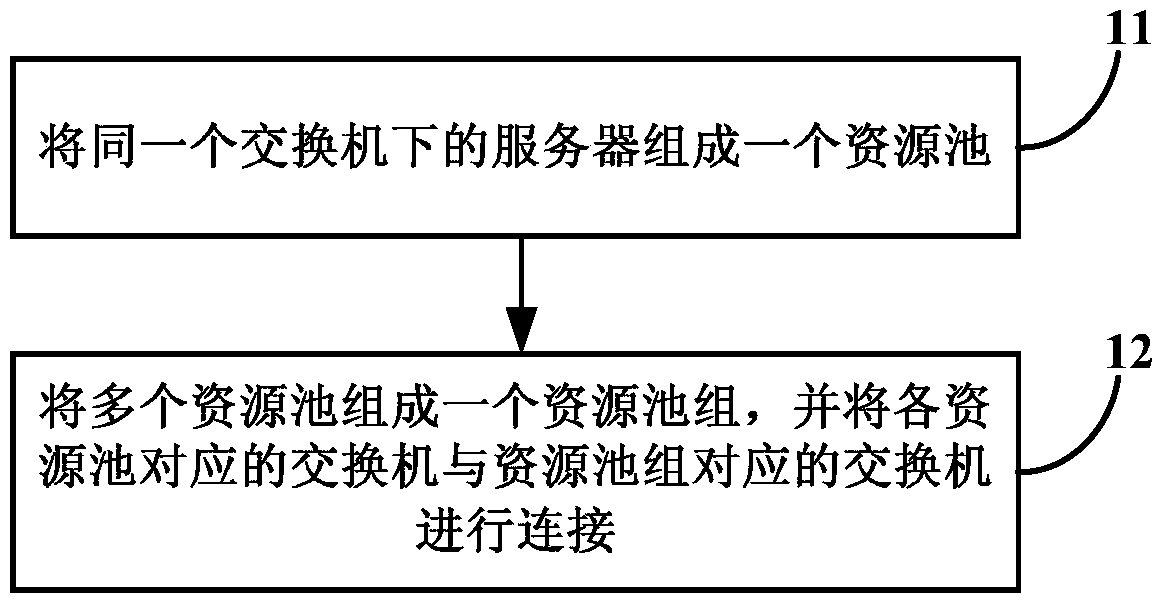
[0021] Figure 1a A schematic flow chart of the cloud system deployment method provided by Embodiment 1 of the present invention, as shown in Figure 1a shown, including:
[0022] Step 11, forming a resource pool of servers under the same switch;
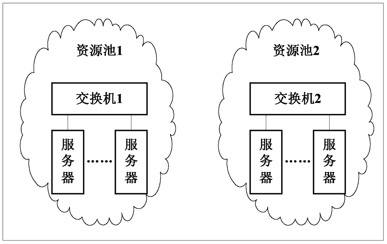
[0023] The executor of the embodiment of the present invention is a cloud platform or a cloud system. The cloud platform or the cloud system searches the switches in the system, obtains the servers connected to each switch, and virtualizes the switches and connected servers to form resources. pool. For example, if Figure 1b As shown, the cloud system builds two resource pools, resource pool 1 and resource pool 2. Resource pool 1 includes switch 1 and multiple servers connected to it, and resource pool 2 includes switch 2 and multiple servers connected to it.
[0024] Step 12, form multiple resource pools into a resource pool group, and connect the switch corresponding to each resource pool with the switch corresponding to the res...
Embodiment 2
[0035] figure 2 A schematic flow chart of the cloud system deployment method provided in Embodiment 2 of the present invention, as shown in figure 2 shown, including:
[0036] Step 21, organize the servers connected to the same switch into a resource pool, and limit the migration of virtual resources only in the resource pool;
[0037] Step 22, binding some private, redundant or cost-insensitive resource configuration information on the switch to the resource pool;
[0038] Step 23, organizing multiple resource pools into a resource pool group, all pool switches are connected to the pool group switches, so that the resource pool groups form an availability domain, and the resource pools are in the same region;
[0039] Step 24: Bind some global, non-redundant or cost-sensitive resource configuration information on the switch to the resource pool group.
[0040] In the embodiment of the present invention, the servers under the same switch are formed into a resource pool, a...
Embodiment 3
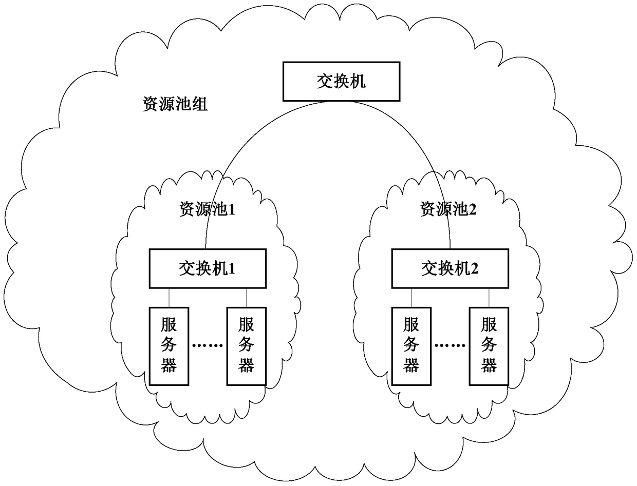
[0042] image 3 A schematic structural diagram of the cloud system provided by Embodiment 3 of the present invention, such as image 3 As shown, it specifically includes: a resource pool 31 and a resource pool group 32;
[0043] The resource pool group 32 is composed of a plurality of resource pools 31;
[0044] The resource pool 31 is composed of servers 312 under the same switch 311;
[0045] The switches 311 corresponding to the multiple resource pools 31 are connected to the switches 321 corresponding to the resource pool group 32 .
[0046] Wherein, there may be multiple resource pool groups in the cloud system, and there may be multiple switches corresponding to one resource pool group.
[0047] The cloud system provided in this embodiment provides setting of resource pools and resource pool groups, and resources are structured and hierarchical, thereby improving resource utilization and security.
[0048] Exemplarily, based on the foregoing embodiments, servers in t...
PUM
 Abstract
Description
Claims
Application Information