Inner blowout prevention double floating valves of double-wall drill pipe

A double-wall drill pipe, double-floating technology, used in earth-moving drilling, wellbore/well valve devices, wellbore/well components, etc. blowout effect

Inactive Publication Date: 2015-08-05
CHINA UNIV OF PETROLEUM (BEIJING)
View PDF5 Cites 14 Cited by
  • Summary
  • Abstract
  • Description
  • Claims
  • Application Information

AI Technical Summary

Problems solved by technology

However, the existing cock-type double floating valve is prone to problems such as seal failure, jamming, lax closure, and difficulty in closing under pressure under high

Method used


Image

  • Inner blowout prevention double floating valves of double-wall drill pipe
  • Inner blowout prevention double floating valves of double-wall drill pipe
  • Inner blowout prevention double floating valves of double-wall drill pipe

Examples


Example Embodiment

[0026] Example one

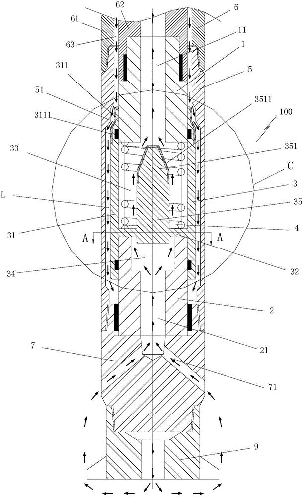
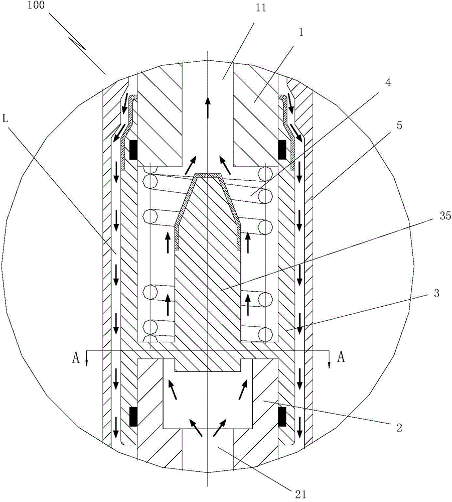
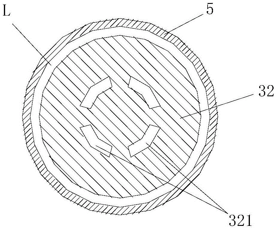
[0027] Such as figure 1 , figure 2 As shown, the present invention proposes a double-walled drill pipe internal blowout prevention double floating valve 100. The double floating valve 100 includes an upper valve seat 1, a lower valve seat 2 and a coaxial slide between the upper and lower valve seats. The floating valve core 3; the upper and lower valve seats are cylindrical, the center of the upper valve seat 1 is provided with a first axial through hole 11, and the center of the lower valve seat 2 is provided with a second axial through hole 21 (in this In an embodiment, the second axial through hole 21 may be a stepped hole with a larger upper portion and a smaller lower portion. The floating valve core 3 includes an outer positioning sleeve 31 coaxially sealed and slidingly arranged on the outer walls of the upper and lower valve seats, The outer layer positioning sleeve 31 is horizontally sealed with a partition plate 32, and the outer layer positioning ...

Example Embodiment

[0034] Example two

[0035] The structure and working principle of this embodiment and the first embodiment are basically the same, and the difference lies in Figure 7 As shown, the upper end of the double floating valve 100 in this embodiment is connected to a first double wall drill rod 6, and the lower end of the double floating valve 100 is connected to a second double wall drill rod 8.

[0036] Such as Figure 7 As shown, the upper outer wall of the valve sleeve 5 and the inner wall of the outer tube 61 of the first double-wall drill rod 6 are threadedly connected, and the lower end inner wall of the valve sleeve 5 is threadedly connected to the outer wall of the outer tube 81 of the second double-wall drill rod 8 , The top end of the upper valve seat 1 is sealed and inserted into the inner tube 62 of the first double-wall drill rod, and the first axial through hole 11 is in communication with the inner tube 62 of the first double-wall drill rod. The bottom end of the lower...


PUM


Abstract

The invention provides inner blowout prevention double floating valves of a double-wall drill pipe. The inner blowout prevention double floating valves comprise an upper valve seat, a lower valve seat and a floating valve core which is arranged between the upper valve seat and the lower valve seat in a coaxial and sliding mode; axial through holes are formed in the center of the upper valve seat and the center of the lower valve seat in a communicated mode respectively; the floating valve core comprises an outer layer positioning sleeve which is arranged on the outer wall of the upper valve seat and the lower valve seat in a coaxial, sealing and sliding mode; a separation plate is horizontally arranged inside the outer layer positioning sleeve in a sealing mode; the center of the separation plate protrudes upward to form a cylindrical plug; a plurality of through holes are annularly formed in the separation plate and surround the cylindrical plug; an elastic element is located on the outer side of the cylindrical plug and arranged between the upper valve seat and the separation plate; a valve sleeve is arranged on the outer side of the upper valve seat, the lower valve seat and the floating valve core in a coaxial mode; a gap formed between the valve sleeve and the outer side of the upper valve seat, the lower valve seat and the floating valve core forms an annular overflow channel. When a blowout is produced in the drilling process, the inner blowout prevention double floating valves can be automatically closed so as to simultaneously close a double-wall drill pipe center drilling fluid overflow channel and an annular space drilling fluid overflow channel formed between an inner pipe and an outer pipe of the double-wall drill pipe and accordingly a blowout and well kick accident is effectively prevented.

Description

technical field [0001] The invention relates to a double-wall drill pipe internal blowout prevention tool for drilling operations, in particular to a double-wall drill pipe internal blowout prevention double floating valve. Background technique [0002] The double-wall drill pipe drilling method is a method of drilling with double-wall drill pipe and other auxiliary drilling equipment. The annular space formed by the inner tube and the outer tube of the double-wall drill pipe provides another channel (flow channel) for fluid flow. In the double-wall drill pipe reverse circulation drilling method, when drilling, the drilling fluid passes through the double-wall drill pipe. The flow channel between the pipe and the outer pipe is injected into the well, and the drilling fluid is sprayed out from the drill bit to clean the wellbore. The drilling fluid carrying the cuttings passes through the flow conversion joint, and returns upward to the ground through the central flow channel...

Claims


Application Information

Patent Timeline
IPC IPC(8): E21B34/08
CPCE21B34/08
Inventor 刘忠郭佳新孟尧
Owner CHINA UNIV OF PETROLEUM (BEIJING)
Why Eureka
Try Eureka