
A braking control method based on recognition of driver's braking intention

A braking control and driver technology, applied in the direction of braking safety system, etc., can solve the problem that the braking system cannot well conform to the driver's true intention, and achieve rapid braking response, quick response, and shortened braking distance. Effect

Inactive Publication Date: 2018-03-13
SHANGHAI UNIV OF ENG SCI
View PDF5 Cites 2 Cited by
  • Summary
  • Abstract
  • Description
  • Claims
  • Application Information

AI Technical Summary

Problems solved by technology

However, the current brake-by-wire system does not analyze the relationship between the driver's intention and the braking intensity, and the actual braking intensity of the braking system cannot better meet the driver's real intention.

Method used


Image

  • A braking control method based on recognition of driver's braking intention
  • A braking control method based on recognition of driver's braking intention
  • A braking control method based on recognition of driver's braking intention

Examples


Embodiment

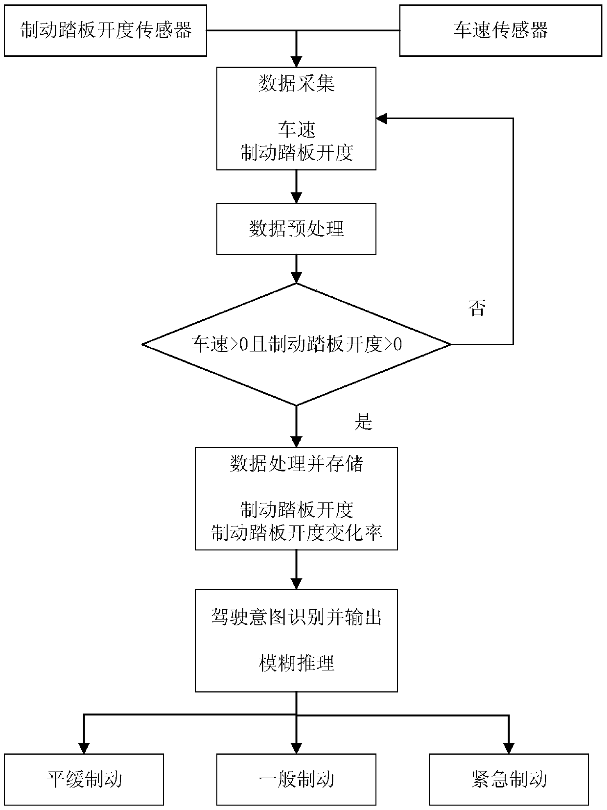
[0043] Such as figure 1 Shown is the recognition process of the driving intention recognition system, which includes a data acquisition module, a data preprocessing module, a pre-recognition judgment module, a data processing module, a data storage module, a driving intention recognition module, and a data output module.

[0044] The data acquisition module includes a vehicle speed sensor and a brake pedal opening sensor. It collects the vehicle speed and brake pedal opening signals in real time and records all values ​​in each sampling period. The collected data is stored in sections after preprocessing. Among them, the sampling period is 0.04s, and the data segmentation time is 1s.

[0045] The data preprocessing module processes the initial data, including data filtering, eliminating abnormal data, and converting the brake pedal opening value into the percentage of its maximum stroke, the range is [0,100], and the unit is the opening percentage (%). The data is converted i...


PUM


Abstract

The invention relates to a brake control method based on driver brake intension recognition. The brake control method comprises the following steps: (1) judging the current brake intension of a driver through fuzzy reasoning according to a brake pedal opening value obtained by a brake pedal opening degree sensor and a vehicle running speed obtained by a vehicle speed sensor, and thus obtaining the representation value of the current brake intension; (2) obtaining a brake control command corresponding to the current brake intension according to the representation value of the current brake intension and the current brake pedal opening value and the vehicle speed of the vehicle, and carrying out corresponding brake actions. Compared with the prior art, the brake control method has the advantages of rapid response, high reliability and the like, the brake potential is developed, and the driving safety is improved.

Description

technical field [0001] The present invention relates to the technical field of automobile braking, in particular to a braking control method based on recognition of driver's braking intention Background technique [0002] Most automobile braking systems use hydraulic or pneumatic braking. In traditional braking systems, when the driver depresses the brake pedal, the piston connecting rod connected to the brake master cylinder is pushed, and the brake master cylinder generates corresponding pressure in the system circuit. , which in turn acts on the brake actuator. Due to the long transmission pipeline of the hydraulic or pneumatic circuit, the brake needs a certain response time, so it is easy to cause the hysteresis phenomenon if the brake is not timely. At the same time, the traditional braking system does not analyze the real intention of the driver, and the braking pressure is only amplified according to the stroke of the brake pedal. , so that the driver lacks a good ...

Claims


Application Information

Patent Timeline
Patent Type & Authority Patents(China)
IPC IPC(8): B60T17/22
CPCB60T17/22
Inventor 向绪爱张缓缓赵培腾谭新佳
Owner SHANGHAI UNIV OF ENG SCI
Learn More