Portable angle ruler

An angle ruler and portable technology, applied in the field of measuring rulers, can solve the problems of deviation, the length ratio between the ruler body and the two ends of the scale, and the inability to arbitrarily predetermine the angle. Effect

Inactive Publication Date: 2015-08-19
付润久
View PDF10 Cites 2 Cited by
  • Summary
  • Abstract
  • Description
  • Claims
  • Application Information

AI Technical Summary

Problems solved by technology

Multi-angle medium and large long-side geometric workpieces need to ensure manufacturing and measurement accuracy, so as to meet the overall accuracy requirements when combining workpieces. Traditional angle rulers cannot be used for workpieces with various angles, line drawing, and blanking. Predetermined angle, the accuracy cannot be guaranteed Angle measurement of the long side of a large workpiece
[0003] The original angle has limitations, see attached Figure 5 , the long-side workpiece cannot be continuously measured, and because the angle of the angle ruler dial cannot be firmly fixed, the length ratio between the ruler body and the two ends of the scale is large, and the calibration is easy to move, resulting in measurement deviation

Method used


Image

  • Portable angle ruler
  • Portable angle ruler
  • Portable angle ruler

Examples


Embodiment 1

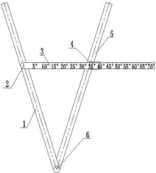
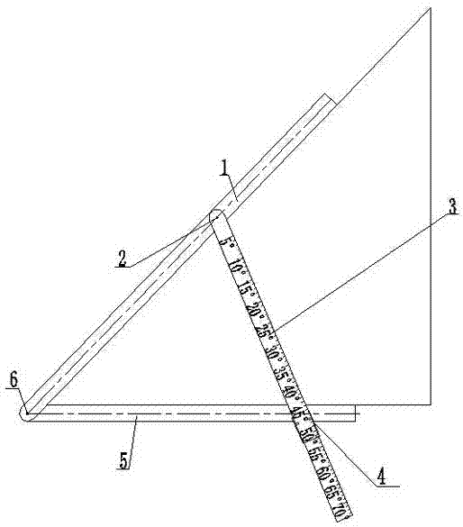
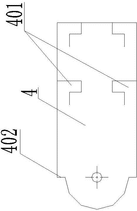
[0021] A portable angle ruler, see attached figure 1 to attach Figure 4 , among the figure: the first base scale 1, the first pin shaft 2, the graduated scale 3, the reading edge 301, the auxiliary scale 4, the claw 401, the reference line 402, the second base scale 5, the second pin shaft 6.

[0022] In this embodiment, the main scale is composed of a first base scale 1 and a second base scale 5, one end of the first base scale 1 and the second base scale 5 is hinged by a second pin shaft 6, and the first base scale 1 is passed through the second base scale 5. A pin shaft 2 is hinged with one end of a graduated ruler 3 .

[0023] The secondary scale 4 is hinged on the second base scale 5, and the other end of the graduated scale 3 passes through the chute on the secondary scale 4 and slides with the chute. The space is the chute; (the claw 401 is processed from the body of the sub-scale 4 by wire cutting and then punching) The height of the chute matches the thickness of ...

Embodiment 2

[0032] Embodiment 2, see attached Figure 6 , Among the figures: the first base scale 1, the first pin shaft 2, the graduated scale 3, the auxiliary scale 4, the second base scale 5, the second pin shaft 6, the first additional chi 7, and the second additional chi 8.

[0033] The difference with embodiment 1 is:

[0034] The outside of the first base ruler 1 (the side away from the second base ruler 5) is hinged with a first additional ruler 7 and a second additional ruler 8, and the first additional ruler 7 and the second additional ruler 8 are provided with the same length. An isosceles triangle structure is formed between the base ruler 1 and the first additional ruler 7 and the second additional ruler 8 .

[0035] The first base scale 1, the graduated scale 3 and the first additional scale 7 share the second pin shaft 2 to be hinged, and the second pin shaft 6 shared by the first base scale 1 and the second base scale 2 is hinged with a second additional scale 8 at one e...


PUM


Abstract

The invention relates to a measuring ruler, especially a portable angle ruler. The angle ruler comprises a main scale, a graduated scale with scale, and an auxiliary scale. The main scale comprises a first base ruler and a second base ruler. The first base ruler is hinged to one end of the second base ruler, and is hinged to one end of the graduated scale. The second base ruler is equipped with the auxiliary scale. The other end of the graduated scale passes through a chute of the auxiliary scale to be in sliding fit with the chute. The first base ruler, the second base ruler and the graduated scale form an isosceles triangle structure. The isosceles triangle serves as the bottom edge of the isosceles triangle structure. Compared with the prior art, the angle ruler is advantageous in that the angle ruler is portable, is convenient to use, can be folded, is precise in angle measurement, is large in measurement range, can be used for directly reading data, and is low in manufacture cost.

Description

technical field [0001] The invention relates to a measuring ruler, in particular to a portable angle ruler. Background technique [0002] In the manufacturing process of the workpiece in the factory, there is no practical and reliable angle ruler for measuring the angle of the long side of the workpiece. Multi-angle medium and large long-side geometric workpieces need to ensure manufacturing and measurement accuracy, so as to meet the overall accuracy requirements when combining workpieces. Traditional angle rulers cannot be used for workpieces with various angles, line drawing, and blanking. For predetermined angles, the accuracy cannot be guaranteed for the angle measurement of the long side of a large workpiece. [0003] The original angle has limitations, see attached Figure 5 , the long-side workpiece cannot be continuously measured, and because the angle of the angle ruler dial cannot be firmly fixed, the length ratio between the ruler body and the two ends of the ...

Claims


Application Information

Patent Timeline
Patent Type & Authority Applications(China)
IPC IPC(8): G01B3/56
Inventor 付润久孙鹏伦侯志钢
Owner 付润久
Why Eureka
Try Eureka