
Method for detecting touched position on touch panel, method for inspecting touch panel, and touch panel inspecting apparatus

A touch position, touch panel technology, applied in the input/output process of data processing, instruments, calculations, etc., can solve the problem of low touch position detection accuracy, and achieve the effect of improving detection accuracy

Inactive Publication Date: 2015-08-19
NIDEC-READ CORPORATION
View PDF9 Cites 4 Cited by
  • Summary
  • Abstract
  • Description
  • Claims
  • Application Information

AI Technical Summary

Problems solved by technology

[0003] However, as described above, the method of detecting the position of the center of gravity of the electrostatic capacitance value of each sensing area as the touch position has a problem of low detection precision of the touch position.

Method used


Image

  • Method for detecting touched position on touch panel, method for inspecting touch panel, and touch panel inspecting apparatus
  • Method for detecting touched position on touch panel, method for inspecting touch panel, and touch panel inspecting apparatus
  • Method for detecting touched position on touch panel, method for inspecting touch panel, and touch panel inspecting apparatus

Examples


Embodiment Construction

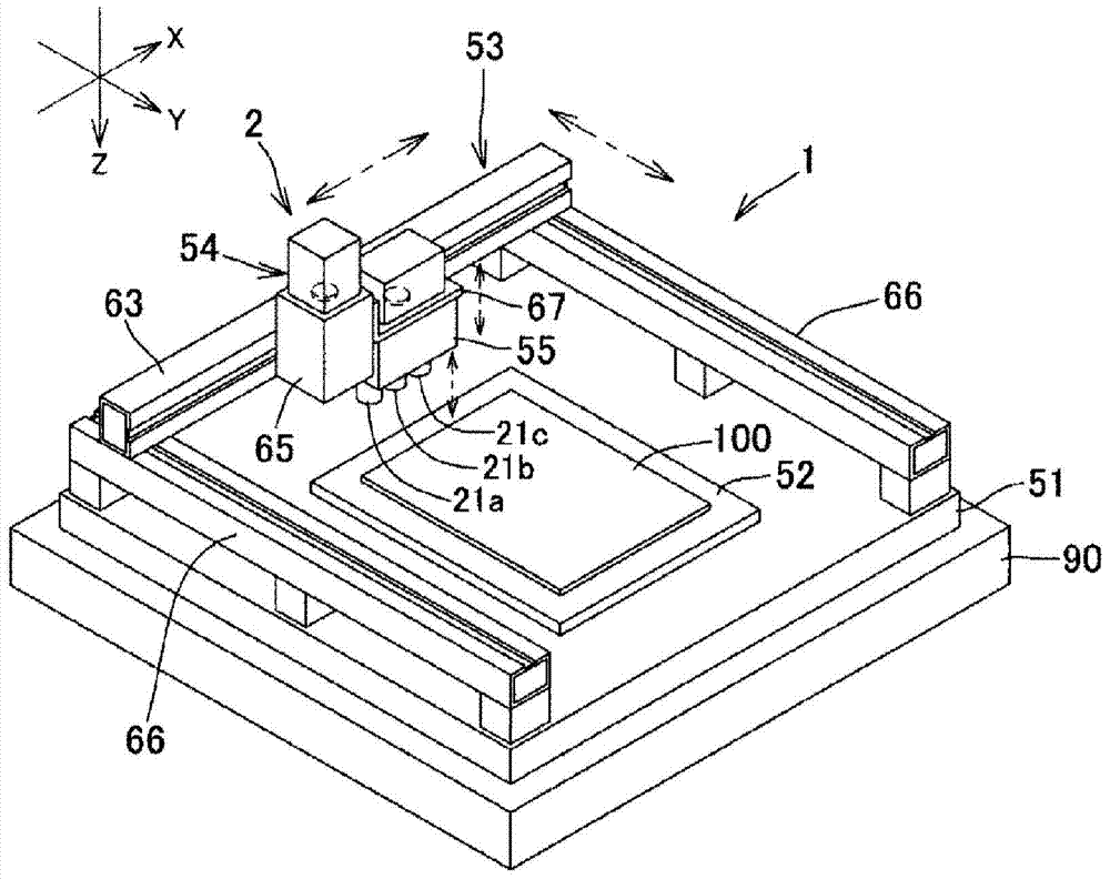
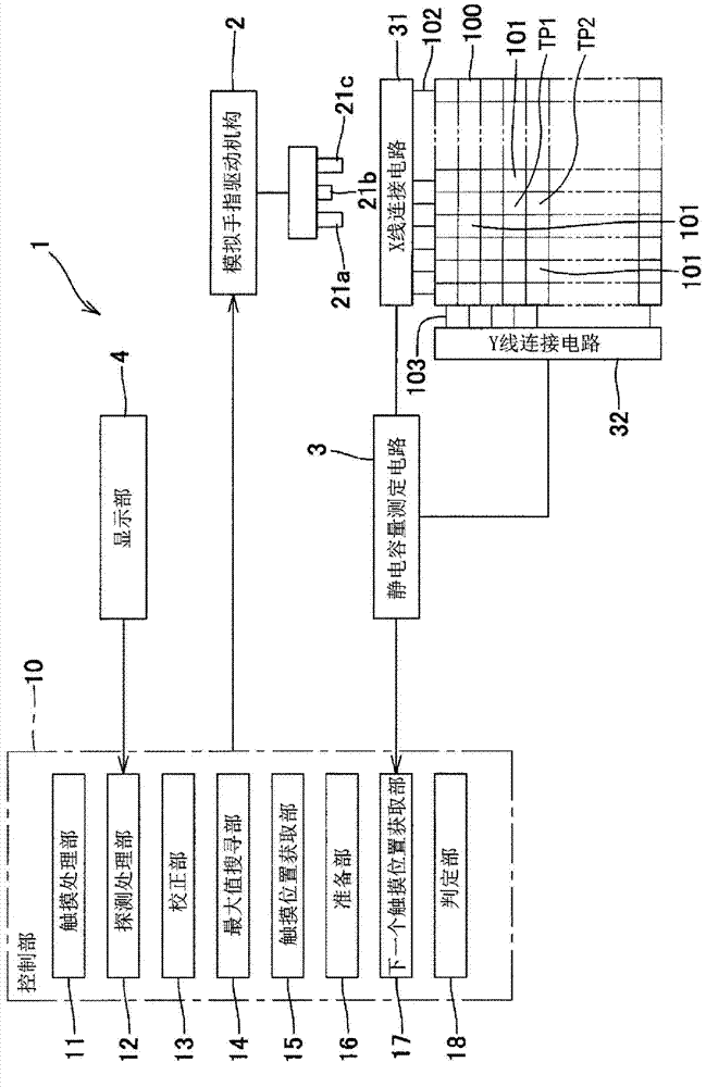
[0060] Hereinafter, embodiments of the present invention will be described in detail with reference to the accompanying drawings. In addition, the same code|symbol is attached|subjected to the same structure in each drawing, and description is abbreviate|omitted. figure 1 It is a perspective view schematically showing an example of the configuration of a touch panel detection device using a touch panel touch position detection method according to an embodiment of the present invention. figure 1 The illustrated touch panel inspection device 1 is disposed on a horizontal substrate 90 .

[0061] The touch panel inspection device 1 includes: a base 51 , a workpiece holder 52 , simulated fingers 21 a , 21 b , 21 c , and a simulated finger drive mechanism 2 (touch mechanism). The simulated finger driving mechanism 2 includes: an XY moving mechanism 53 , a Z moving mechanism 54 , and a simulated finger mechanism 55 . The upper surface of the base 51 forms a horizontal plane, and mu...


PUM


Abstract

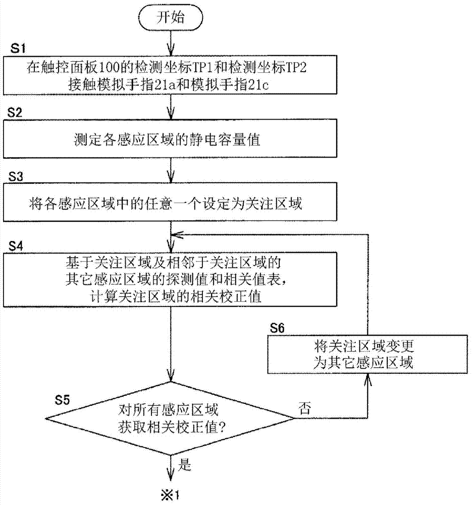
A method for detecting a touched position on a touch panel (100) includes: acquiring a capacitance value (S2, 3) detected in each sensing area (101) of the touch panel; correcting each capacitance value (13), based on a correlation value table (6) that stores therein a numerical influence to be exerted on the capacitance value in each sensing area by the capacitance value in the sensing area adjacent to each sensing area, and calculating a correlation correction value for each sensing area (S4); retrieving the maximum value from among the correlation correction values (S12, 14); and defining the sensing area for which the correlation correction value is the maximum value, as a maximum area, calculating a centroid position as to an area including the maximum area and the sensing areas adjacent to the maximum area, based on the correlation correction values (S16), and acquiring the calculated centroid position as a touched position (S17, 15).

Description

technical field [0001] The invention relates to a touch position detection method for detecting a touch position of a touch panel, a touch panel detection method using the touch position detection method, and a touch panel detection device. Background technique [0002] In the past, the known touch panel detects the touch position by using the center of gravity method. The center of gravity method is to calculate the center of gravity position of the electrostatic capacitance value of a plurality of sensing areas by measuring the electrostatic capacitance of the sensing areas arranged in a grid shape (for example, , refer to Patent Document 1). [0003] However, as described above, the method of detecting the position of the center of gravity of the capacitance value of each sensing region as the touch position has a problem of low detection precision of the touch position. [0004] [Prior Art Literature] [0005] 【Patent Document 1】 [0006] Patent Document 1: Japanese P...

Claims


Application Information

Patent Timeline
Patent Type & Authority Applications(China)
IPC IPC(8): G06F3/041G06F3/044
CPCG06F2203/04104G06F3/044G06F3/0418G06F3/0446G06F3/0416
Inventor 楠田达文本田睦博栗原靖人
Owner NIDEC-READ CORPORATION
Learn More