

Relay multifunctional detection machine
A multi-functional, testing machine technology, applied in circuit breaker testing, electrical measuring instrument parts and instruments, etc., can solve the problem of affecting relay safety, large deviation of relay testing data, and interference of current collector plate turbulence. It can improve the detection precision, improve the failure of individual contacts, and ensure the safety factor.
- Summary
- Abstract
- Description
- Claims
- Application Information
AI Technical Summary
Problems solved by technology
Method used
Image

Examples
Embodiment 1
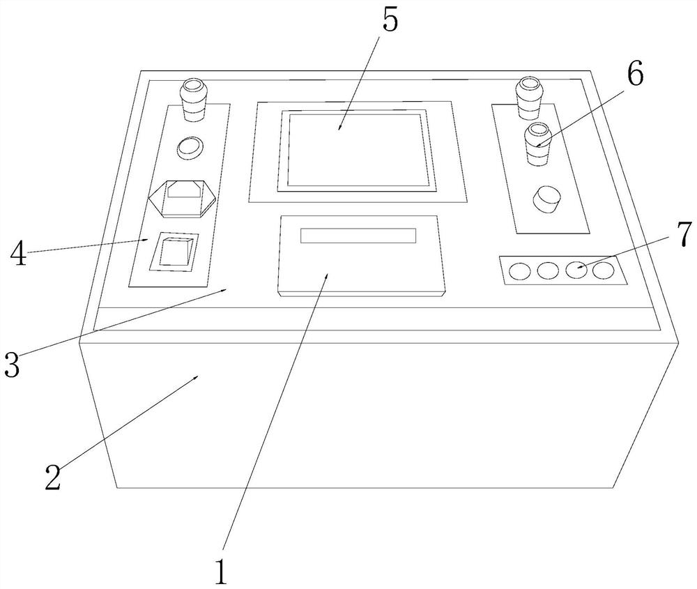
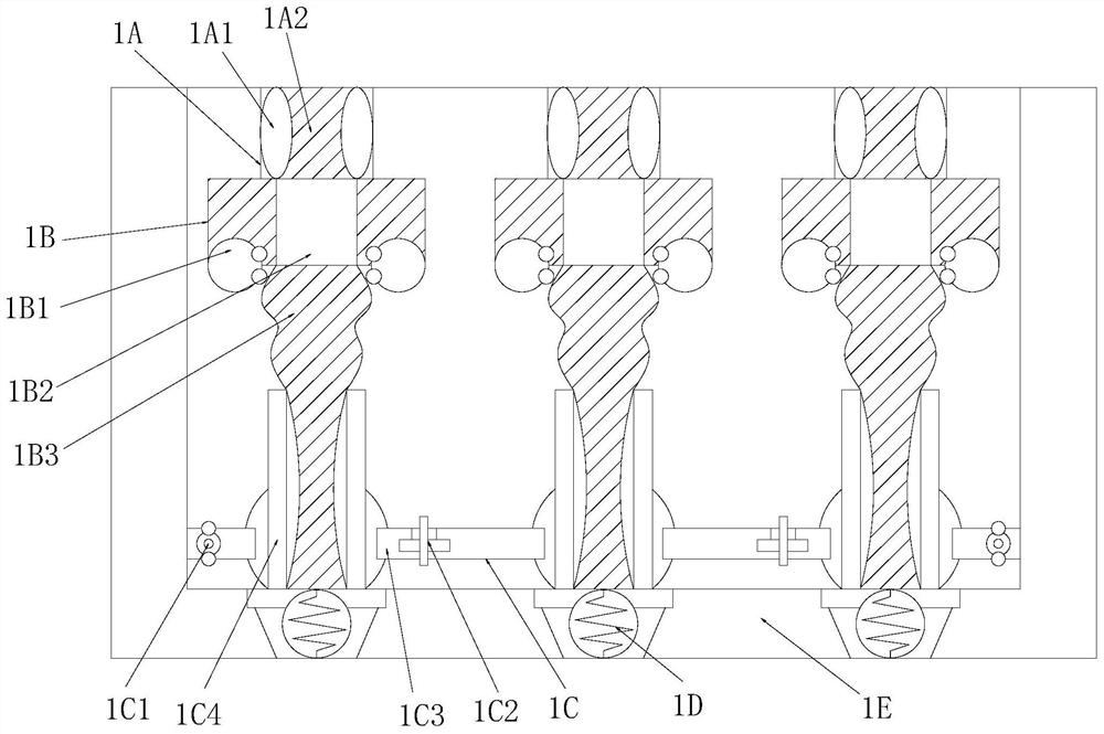
[0032] see Figure 1-Figure 6 , the present invention provides a relay multifunctional detection machine, the structure of which includes: a relay detection slot 1, a box housing slot seat 2, an integrated circuit board 3, a power switch board 4, a man-machine interface screen 5, and a terminal cylinder 6 , button key board 7, the relay detection slot 1 is installed in the inside of the case housing seat 2, the integrated circuit board 3 is nested on the top of the case case seat 2, the power switch board 4 and The button key boards 7 are respectively installed on the left and right sides of the man-machine interface screen 5 and are on the same horizontal plane. The terminal cylinder 6 is embedded in the upper right corner of the integrated circuit board 3 and is perpendicular to each other. The relay detection slot 1 is provided with a collector plate pad cylinder 1A, a pin end belt ring 1B, a splint rail frame 1C, a trapezoidal Ball spring seat 1D, concave slot 1E, the tra...
Embodiment 2
[0038] see Figure 1-Figure 6 , the present invention provides a kind of relay multifunctional detection machine, other respects are identical with embodiment 1, and difference is:
[0039] see figure 2 , the splint rail frame 1C is composed of a tie rod ball wheel seat 1C1, a rotor shuttle block 1C2, a rail groove bar 1C3, and a convex pad splint 1C4, and the tie rod ball wheel seat 1C1 is fastened together with the rail groove bar 1C3 , the rotor shuttle block 1C2 is mechanically connected to the cross rail groove bar 1C3, the cross rail groove bar 1C3 is welded together with the convex pad splint 1C4 and is perpendicular to each other, and the horizontal rail groove bar 1C3 is inserted into the convex pad splint 1C4 to form a lateral Effect of septum holder and longitudinally interspersed pins.
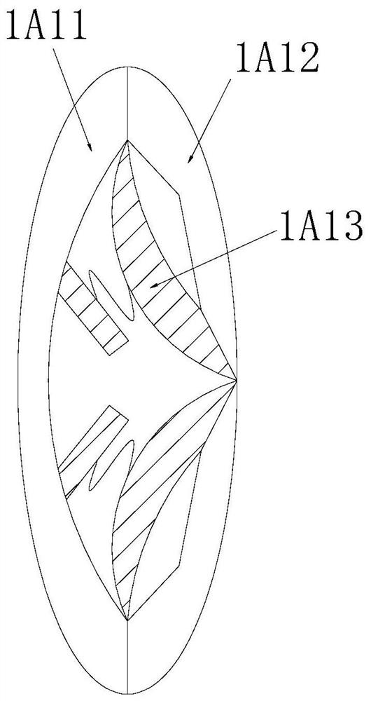
[0040] see Figure 5 , the tie rod ball wheel seat 1C1 is composed of an arc valve ball groove 1C11, a frame tie rod column 1C12, and a wheel ring seat 1C13, and the arc valve ...
PUM
 Abstract
Description
Claims
Application Information