High-power rolling type collector ring device

A slip ring and rolling type technology, which is applied in the field of high-power rolling slip ring devices, can solve the problems of increased cost, high requirements for selection and assembly, and achieve the effects of reducing manufacturing costs, expanding the scope, and increasing the reliability of use

Inactive Publication Date: 2015-08-19
CHINA ACADEMY OF SPACE TECHNOLOGY
View PDF6 Cites 13 Cited by
  • Summary
  • Abstract
  • Description
  • Claims
  • Application Information

AI Technical Summary

Problems solved by technology

The roller uses a thin-walled elastic ring. Since the wall thickness must not only meet the electrical path impedance, but also must achieve the required radial stiffness and stress requirements to meet the required fatigue life requirements, the selection of materials and assembly requirements are more demanding. high, cost increase

Method used


Image

  • High-power rolling type collector ring device
  • High-power rolling type collector ring device
  • High-power rolling type collector ring device

Examples


Embodiment Construction

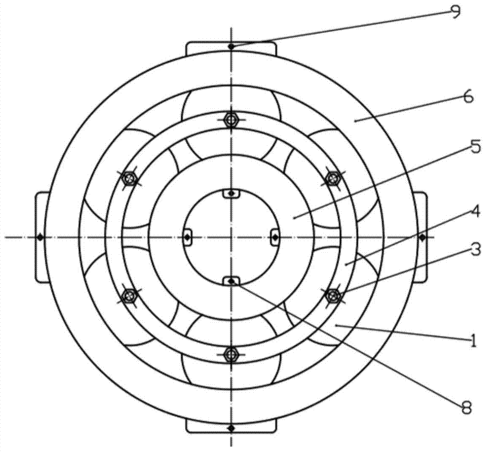
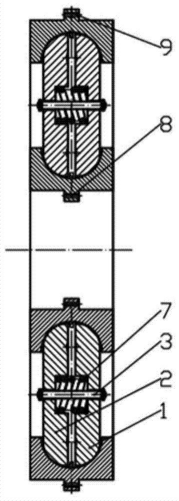
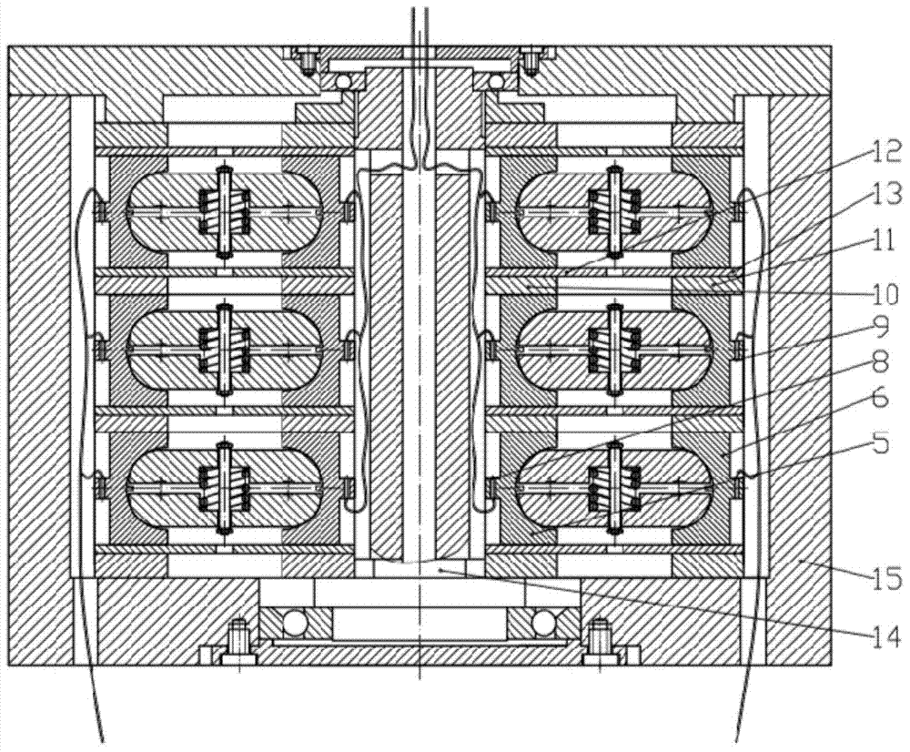
[0019] The present invention proposes a high-power rolling slip ring device, such as figure 1 , figure 2 As shown, a high-power rolling slip ring device of the present invention includes a first coupling 1, a second coupling 2, a coupling shaft 3, a cage 4, an inner ring 5, an outer ring 6, a spring 7, and a first ear hole 8 , the second ear hole 9, the first support frame 10, the second support frame 11, the inner insulating plate 12, the outer insulating plate 13, the main shaft 14 and the box body 15.

[0020] The first coupler 1 and the second coupler 2 are circular truncated structures, and the center of the other end is provided with a cavity, and the couplers are used in pairs; the coupling shaft 3 is installed in the middle of the paired first coupler 1 and second coupler 2 In the cavity, connect the first coupler 1 and the second coupler 2 two by two, and constrain the first coupler 1 and the second coupler 2 to only rotate and move axially along the coupling shaft ...


PUM


Abstract

The invention provides a high-power rolling type collector ring device comprising first connectors (1), second connectors (2), connecting shafts (3), maintaining frames (4), internal rings (5), external rings (6), springs (7), first ear holes (8), second ear holes (9) and main shafts (14). The connecting shafts (3) and the springs (7) are arranged between pairs of the first connectors (1) and the second connectors (2), and the side surface ends of the first connectors (1) and the side surface ends of the second connectors (2) are pressed to the internal side surface of the grooves of the internal rings (5) and the internal side surfaces of the grooves of the external rings (6) so that current and signal transmission is completed. The springs are installed in the pairs of the connectors of connector rings, and the side surfaces of the connectors are enabled to be contacted with rails via the springs without major influence on fatigue and elasticity of the connectors so that the service life is prolonged. Meanwhile, only the conduction characteristic is considered in connector ring material selection so that material selection range is enlarged.

Description

technical field [0001] The invention relates to a signal and power transmission device between full-degree-of-freedom rotating mechanisms, in particular to a high-power rolling slip ring device. Background technique [0002] The slip ring is a device for transmitting signals and power between two full-degree-of-freedom rotating mechanisms. It is an essential and important part of equipment such as satellites, radars, and space stations. The transmission performance and service life of the slip ring directly affect the performance of these devices. and longevity. At present, the slip ring mainly includes a sliding slip ring and a rolling slip ring, among which [0003] The manufacturing technology of the sliding collector ring is relatively mature, and it is being widely used on the interface of two full-degree-of-freedom rotating mechanisms. However, the friction torque of the sliding collector ring is relatively large, and the sliding contact method causes serious surface ...

Claims


Application Information

Patent Timeline
Patent Type & Authority Applications(China)
IPC IPC(8): H01R39/64H01R39/28
Inventor 刘自立马春生李瑞琴李虹王立侯欣宾李萌
Owner CHINA ACADEMY OF SPACE TECHNOLOGY
Why Eureka
Try Eureka