Protection cover of conical base of ship

A conical and protective cover technology, which is applied to ships and other directions, can solve the problems of being vulnerable to erosion, unfavorable base maintenance, and difficult to effectively resist the threat of natural phenomena, and achieve the effect of strengthening sealing and quick disassembly

Inactive Publication Date: 2015-08-26
CSSC HUANGPU WENCHONG SHIPBUILDING COMPANY
8 Cites 4 Cited by

AI-Extracted Technical Summary

Problems solved by technology

[0004] Although the canvas cover in the prior art meets the requirements of not damaging the conical base itself, it is difficult to effecti...

Method used

In this embodiment, the circular cover plate 200 is fitted on the annular cover plate 110 of the conical base 100 through the annular groove 240 formed between two groups of first reinforcing materials 210, which can greatly strengthen Sealing, effectively resisting the threats of various natural phenomena; the first end of the fastener 250 is connected to the circular cover plate 200 by a bolt 260, and the second end can be buckled on the ring of the conical base 100 On the reinforcing plate 120, the protective cover is integrally fastened on the conical base 100 in the manner of buckling, avoiding the use of destructive protection methods such as welding, and can be quickly disassembled (only need to unscrew the bolt 260 during disassembly) That is,) will not damage the conical base 100 itself. In addition, in this embodiment, a gasket 230 is provided in the annular groove 240 and between the circular cover plate 200 and the annular cover plate 110, which can prevent the circular cover plate 200 and the annular cover plate 110 from being assembled or disassembled. The problem of damage to both caused by collision during use.
[0022] In this embodiment, the second end of the fastener 250 is preferably U-shaped; it is adapted to be buckled on the annular reinforcement plate 120 of the conical base 100. The U-shaped design has the advantag...

Abstract

The invention relates to a protection cover of a conical base of a ship. The protection cover is used for covering the conical base of the ship, and an annular cover plate with an opening in the middle is arranged on the upper end face of the conical base; an annular reinforcing plate is perpendicularly arranged at the bottom of an inner ring of the annular cover plate, and the protection cover comprises a round cover plate, first reinforcing materials, a gasket ring and a fastening part; the first reinforcing materials are annularly fixed to the lower surface of the round cover plate, and an annular groove is formed between the two first reinforcing materials; the annular cover plate of the conical base is sleeved with the annular groove in a matched manner, and the gasket ring is fixed to the annular groove and is located between the round cover plate and the annular cover plate; the first end of the fastening part is in bolt connection with the round cover plate, and the second end of the fastening part is clamped and buckled on an annular reinforcing plate of the conical base; and the protection cover is wholly fastened on the conical base. Threads of various natural phenomena can be effectively resisted, and the conical base can be rapidly dismounted and cannot be damaged.

Application Domain

Technology Topic

Image

  • Protection cover of conical base of ship
  • Protection cover of conical base of ship
  • Protection cover of conical base of ship

Examples

  • Experimental program(1)

Example Embodiment

[0019] In order to facilitate the understanding of those skilled in the art, the present invention will be further described below in conjunction with the accompanying drawings and embodiments.
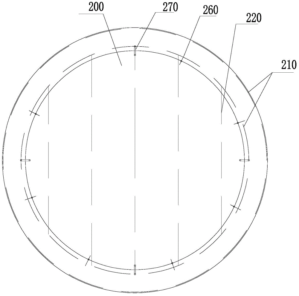
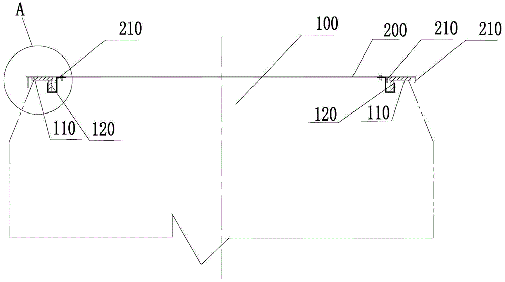
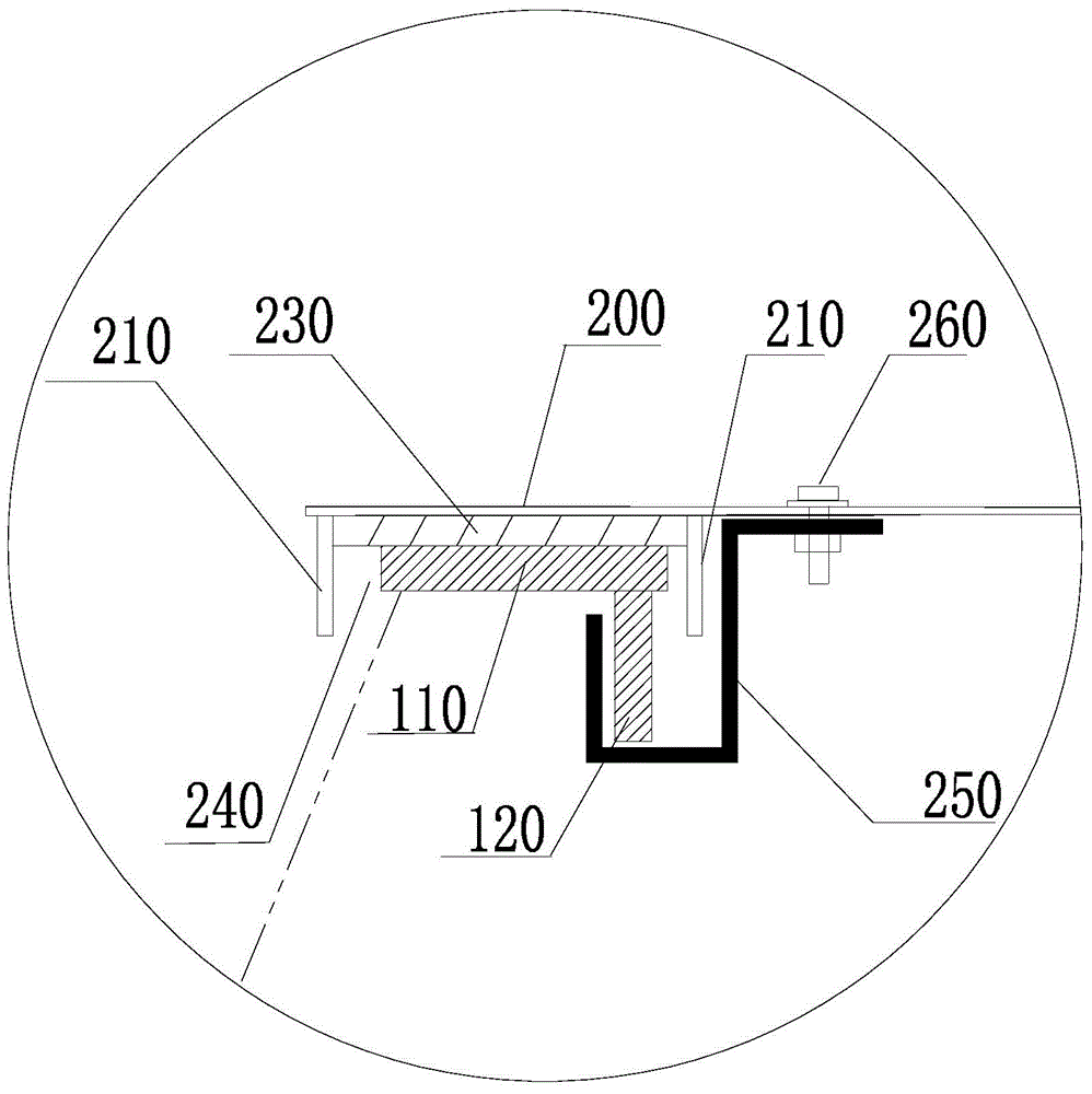
[0020] Please also refer to Figure 1 to Figure 3 , the present embodiment proposes a protective cover for a conical base on a ship, which is used to cover the conical base on a ship. Specifically, it can be as follows figure 2 As shown in the conical base 100, the upper end surface of the conical base 100 is an annular cover plate 110 with a middle opening, and the bottom of the inner ring of the annular cover plate 110 is vertically provided with an annular reinforcing plate 120; The protective cover includes (see image 3 ) a circular cover plate 200, a first reinforcing material 210, a washer 230, and a fastener 250; the first reinforcing material 210 is annularly fixed on the lower surface of the circular cover plate 200, and two groups of first reinforcing An annular groove 240 is formed between the materials 210; the annular groove 240 can be fitted on the annular cover plate 110 of the conical base 100; the gasket 230 is fixed on the annular groove 240, located between the circular cover 200 and the annular cover 110; the first end of the fastener 250 is connected to the circular cover 200 by a bolt 260, and the second end is buckled On the annular reinforcing plate 120 of the conical base 100 , the protective cover is integrally fastened on the conical base 100 .
[0021] In this embodiment, the circular cover plate 200 is fitted on the annular cover plate 110 of the conical base 100 through the annular groove 240 formed between the two sets of first reinforcing members 210, which can greatly enhance the sealing performance. Effectively resist the threat of various natural phenomena; the first end of the fastener 250 is connected to the circular cover plate 200 through bolts 260, and the second end can be buckled on the annular reinforcement plate 120 of the conical base 100 , that is, the protective cover is integrally fastened on the conical base 100 in the manner of buckling, avoiding the use of destructive protection methods such as welding, and can be quickly disassembled (only need to unscrew the bolt 260 during disassembly, ) will not damage the conical base 100 itself. In addition, in this embodiment, a gasket 230 is provided in the annular groove 240 and between the circular cover plate 200 and the annular cover plate 110, which can prevent the circular cover plate 200 and the annular cover plate 110 from being assembled or disassembled. The problem of damage to both caused by collision during use.
[0022] In this embodiment, the second end of the fastener 250 is preferably U-shaped; it is adapted to be buckled on the annular reinforcing plate 120 of the conical base 100 . The U-shaped design has the advantages of being easy to manufacture and convenient to fasten and disassemble.
[0023] In order to ensure the strength of the protective cover, the protective cover may also include a second reinforcing material 220, the second reinforcing material 220 is fixed on the lower surface of the circular cover plate 200, and is located at the top of the first reinforcing material 210. In the inner ring (in this embodiment, specifically, in the inner ring of the innermost first reinforcing material 210), so as to improve the overall strength of the protective cover.
[0024] Since the protective cover of this embodiment is mainly applied on a large conical base, the overall weight of the protective cover is naturally larger, therefore, the protective cover preferably also includes a suspension ring 270 (refer to figure 1 ), the lifting ring 270 is fixed on the upper surface of the circular cover plate 200, and the protective cover can be lifted through the lifting ring 270 by mechanical equipment for installation or removal during use.
[0025] In specific manufacturing, the gasket 230 is preferably a flexible gasket, specifically a rubber gasket. Specifically, the fastener 250 can be made of flat steel. The circular cover plate 200, the first reinforcing material 210 and the second reinforcing material 220 can all be made of steel, and the first reinforcing material 210 and the second reinforcing material 220 can be fixed on the circular cover plate 200 by welding. On the cover plate 200 , of course, the first reinforcing material 210 and the second reinforcing material 220 may also be integrally formed with the circular cover plate 200 . In addition, the lifting ring 270 is also preferably made of steel, which is welded on the upper surface of the circular cover plate 200 to ensure the load-bearing strength.
[0026] The protective cover of the present embodiment can be specifically applied to the protection of the main gun base of a special operation ship such as a coast guard ship, and certainly can also be used for a base of other purposes or a conical base of other types of ships, as long as The structural features similar to those of the conical base 100 in this embodiment can be applicable.
[0027] The above-mentioned embodiments only express several implementation modes of the present invention, and the description thereof is relatively specific and detailed, but should not be construed as limiting the patent scope of the present invention. It should be pointed out that those skilled in the art can make several modifications and improvements without departing from the concept of the present invention, and these all belong to the protection scope of the present invention. Therefore, the protection scope of the patent for the present invention should be based on the appended claims.

PUM

no PUM

Description & Claims & Application Information

We can also present the details of the Description, Claims and Application information to help users get a comprehensive understanding of the technical details of the patent, such as background art, summary of invention, brief description of drawings, description of embodiments, and other original content. On the other hand, users can also determine the specific scope of protection of the technology through the list of claims; as well as understand the changes in the life cycle of the technology with the presentation of the patent timeline. Login to view more.

Similar technology patents

Seal for high-pressure pumping system

InactiveUS6918595B2Reduce and minimize and prevent O-ring abrasionImprove sealingEngine sealsPiston ringsEngineeringHigh pressure
Owner:DIONEX CORP

Open-bottom automatic discharging tank device

InactiveCN101746580AImprove sealingRealize automatic unloadingFlexible coversWrappersCharge and dischargeCushion
Owner:TAIYUAN UNIVERSITY OF SCIENCE AND TECHNOLOGY

Classification and recommendation of technical efficacy words

  • Improve sealing
  • Quick release

Embolic filter frame having looped support strut elements

InactiveUS20040093012A1Longitudinal compliance be enhanceImprove sealingSurgeryDilatorsEngineeringLower degree
Owner:WL GORE & ASSOC INC

Variable frequency automated capacitive radio frequency (RF) dielectric heating system

InactiveUS20020047009A1Improve sealingLowering gap impedanceMeat/fish preservation by heatingDielectric heating circuitsRadio frequencyHeating system
Owner:THE STATE OF OREGON ACTING BY & THROUGH THE OREGON STATE BOARD OF HIGHER EDUCATION ON BEHALF OF OREGON STATE UNIV +1

Orthopedic external fixation device

ActiveUS8257353B2Quick releaseInvalid friendly devicesFractureEngineeringExternal fixator
Owner:WRIGHT MEDICAL TECH

People also interested in

Why Eureka
Try Eureka