Sound source direction estimation apparatus and sound source direction estimation method

A technology of direction estimation and equipment, which is applied to the orientation device for measuring the direction, the system for determining the direction or offset, and the direction finder using ultrasonic/sonic/infrasonic waves, etc., which can solve obstacles, low computing power, and large amount of computing question

Inactive Publication Date: 2015-08-26
KK TOSHIBA
View PDF1 Cites 90 Cited by
  • Summary
  • Abstract
  • Description
  • Claims
  • Application Information

AI Technical Summary

Problems solved by technology

[0005] However, in the conventional technique of estimating the direction of the sound source using the phase difference distribution, the amount of calculation required for the processing of obtaining the direction from the phase difference distribution is large, thereby preventing real-time estimation of the sound source using a device with low computing power. source direction

Method used


Image

  • Sound source direction estimation apparatus and sound source direction estimation method
  • Sound source direction estimation apparatus and sound source direction estimation method
  • Sound source direction estimation apparatus and sound source direction estimation method

Examples


no. 1 example

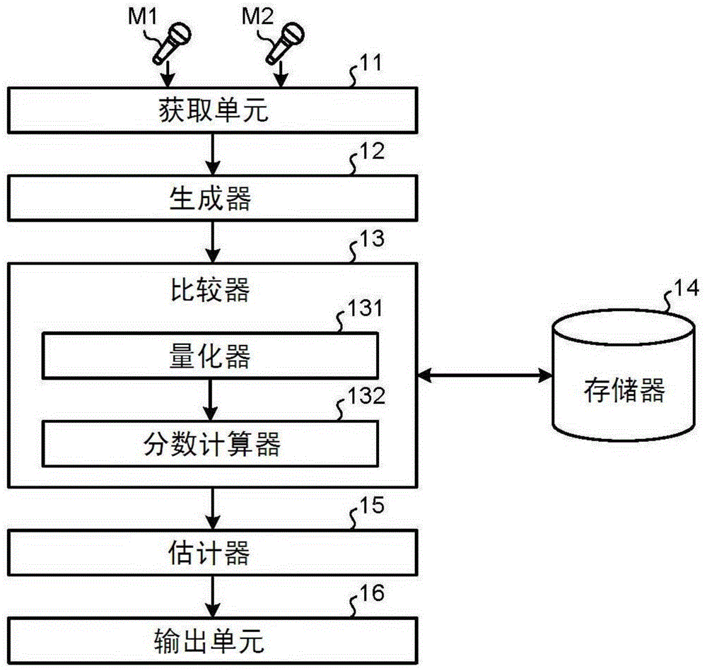
[0033] figure 1 is a block diagram illustrating an example of the functional configuration of the sound source direction estimating device according to the first embodiment. like figure 1 In the middle diagram, the sound source direction estimation device according to the present embodiment includes an acquisition unit 11 , a generator 12 , a comparator 13 , a memory 14 , an estimator 15 and an output unit 16 .

[0034] The acquisition unit 11 acquires acoustic signals of a plurality of channels from a plurality of microphones constituting a microphone array. In this example, if figure 1 As illustrated in , two channels of acoustic signals are acquired from two microphones M1 and M2. The two microphones M1 and M2 constituting the microphone array have a fixed relative positional relationship, and the distance between these two microphones does not change. When the sound source is a person (speaker), for example, the acoustic signal is a voice signal such as the talk of the...

no. 2 example

[0071] Next, a second embodiment will be described. In the first embodiment described above, the score for each direction is calculated by giving equal partial scores to the frequency bins for which the quantized phase difference distribution coincides with the template, and accumulating these partial scores. However, performance, noise, reverberation, etc. of the microphones M1 and M2 sometimes cause abnormal values ​​to be generated in the phase difference distribution. This outlier can have an adverse effect on the estimation of the direction of the sound source. In order to solve this concern, in this embodiment, for each frequency window, an additional score is set, so as to calculate the sum of the additional scores set for each frequency window whose quantized phase difference distribution is consistent with the template, as the sum of the additional scores to be Compare the scores in the directions corresponding to the templates. Thus, the influence of outliers is su...

no. 3 example

[0084] Next, a third embodiment will be described. In the first embodiment described above, all the templates in the respective directions stored in the memory 14 are sequentially read as comparison objects of the quantized phase difference distribution for processing. However, when the angular resolution requested by the user is lower than the angular resolution of the direction in which templates have been prepared in advance, it is not necessary to use all the templates as comparison objects for processing. Therefore, in this embodiment, in order to further reduce the amount of calculation, the user's designation of the angular resolution is accepted, and the number of templates corresponding to the designated angular resolution is selected for processing.

[0085] Hereinafter, part of the features of the present embodiment will be described while appropriately omitting repeated description of constituent parts common to those in the first embodiment by assigning the same r...


PUM


Abstract

According to an embodiment, a sound source direction estimation apparatus includes an acquisition unit, a generator, a comparator, and an estimator. The acquisition unit is configured to acquire acoustic signals of a plurality of channels from a plurality of microphones. The generator is configured to calculate a phase difference of the acoustic signals of the plurality of channels for each predetermined frequency bin to generate a phase difference distribution. The comparator is configured to compare the phase difference distribution with a template generated in advance for each direction, and calculate a score in accordance with similarity between the phase difference distribution and the template for each direction. The estimator is configured to estimate a direction of a sound source based on the scores calculated.

Description

[0001] Cross References to Related Applications [0002] This application is based upon and claims the benefit of priority from Japanese Patent Application No. 2014-036032 filed on February 26, 2014; the entire contents of which are hereby incorporated by reference. technical field [0003] Embodiments described herein generally relate to a sound source direction estimation device and a sound source direction estimation method. Background technique [0004] As a technique for accurately estimating the direction of a sound source without depending on the distance from the sound source to the microphone, there is a technique using phase difference distributions generated from acoustic signals of a plurality of channels. The phase difference distribution is a distribution representing the phase difference of each frequency of the acoustic signal for a plurality of channels, and has a specific characteristic depending on the direction of the sound source in accordance with the d...

Claims


Application Information

Patent Timeline
Patent Type & Authority Applications(China)
IPC IPC(8): G01S3/808
CPCH04R29/00G01S3/8083H04R1/406H04R2430/23
Inventor 丁宁木田祐介
Owner KK TOSHIBA
Why Eureka
Try Eureka