On-board control device

A technology of control devices and camera devices, applied in optical observation devices, vehicle parts, transportation and packaging, etc., can solve problems such as decreased accuracy, lane recognition or parking frame accuracy

Active Publication Date: 2015-08-26
CLARION CO LTD
View PDF6 Cites 2 Cited by
  • Summary
  • Abstract
  • Description
  • Claims
  • Application Information

AI Technical Summary

Problems solved by technology

In such technologies, when raindrops or dirt adhere to the imaging device (camera), the accuracy of white line recognition

Method used


Image

  • On-board control device
  • On-board control device
  • On-board control device

Examples


Embodiment Construction

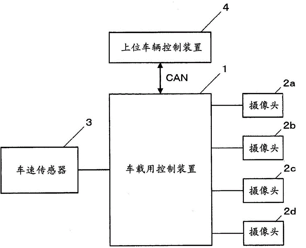
[0027] figure 1 It is a block diagram showing an in-vehicle control device 1 according to an embodiment of the present invention. figure 1 The illustrated in-vehicle control device 1 is mounted on a vehicle for use, and is connected to cameras 2a, 2b, 2c, 2d and a vehicle speed sensor 3. In addition, it is connected to the upper-level vehicle control device 4 via CAN (Controller Area Network).

[0028] The cameras 2a to 2d are composed of, for example, imaging elements such as CCD or CMOS, peripheral circuits, optical lenses, and the like, and are installed on various parts of the vehicle body, bumper, and rearview mirror. These cameras 2a to 2d are referred to as imaging devices.

[0029] The cameras 2a to 2d respectively take images (photographs) of the surroundings of the vehicle in different imaging ranges. The imaging range of each of these cameras is determined to cover the entire periphery of the vehicle in total. In this embodiment, the camera 2a captures the camera range...


PUM


Abstract

An on-board control device is provided with: an image acquisition unit that acquires an image obtained by an imaging device that images an area around a vehicle; a decision area division unit that divides a predetermined decision range of an imaging range of the imaging device into a plurality of areas; a feature point extraction unit that extracts, from the image acquired by the image acquisition unit, a feature point with a predetermined feature around the vehicle; a score accumulation unit that accumulates, with respect to a plurality of images chronologically acquired by the image acquisition unit, a score for an area of the plurality of areas in which the feature point extracted by the feature point extraction unit is present; and a decision unit that makes a decision as to whether foreign matter is attached in the imaging device on the basis of the result of accumulated scores for the plurality of areas.

Description

Technical field [0001] The present invention relates to an in-vehicle control device that is mounted on a vehicle and performs foreign matter adhesion determination in an imaging device that captures images around the vehicle. Background technique [0002] In the past, it has been known to use images captured by a camera mounted on a vehicle (camera) to recognize white lines in a lane or parking lot, and to apply these recognition results to lane recognition or parking frame detection. . In such a technique, when raindrops, dirt, or the like adhere to the camera (camera), the accuracy of white line recognition of the lane or parking lot is reduced, and the accuracy of lane recognition or parking frame detection is reduced. Therefore, various methods of detecting adhesion of raindrops, dirt, etc., of an imaging device (camera) are provided (Patent Document 1). [0003] Prior art literature [0004] Patent literature [0005] Patent Document 1: JP 2012-166705 A Summary of the invent...

Claims


Application Information

Patent Timeline
IPC IPC(8): H04N5/225B60R21/00G03B15/00G08G1/16
CPCH04N5/2171B62D15/028B62D15/0285H04N23/811G06V20/588B60R1/00G06T7/20
Inventor 竹村雅幸绪方健人伊藤哲司
Owner CLARION CO LTD
Why Eureka
Try Eureka