
Phase transition temperature adjusting system and phase transition temperature adjusting cup

A technology of temperature regulation system and temperature regulation cup, which is applied in the direction of drinking water vessels, etc., can solve the problems of low temperature control accuracy, many limiting factors in the use process, complex system, etc., and achieve simple structure, easy operation, and little external environment influence Effect

Active Publication Date: 2015-09-09
YUTIAN ENERGY CO LTD
View PDF6 Cites 60 Cited by
  • Summary
  • Abstract
  • Description
  • Claims
  • Application Information

AI Technical Summary

Benefits of technology

This new type of container called Phase Change Temperature Regulate Cup (PCRF), which combines two materials - one made up mostly of paraffin waxes or similar substances and another solidifying agent like calcium carbonate into what's now known as a gelled state. These types of containers have several technical benefits compared to previous designs such as ice cooled cups and bottles. They are easier to use because they only require once per day to adjust their temperatures while still being able to keep them warm properly even when exposed outside during transportation. Additionally, these devices allow users to control how much liquid inside them based on factors like pressure applied through different parts of the device.

Problems solved by technology

Technological Problem addressed in this patented technical problem includes how to create efficient thermal regulators that allow users to quickly set their desired temperature while maintaining accurate measurement over various conditions such as ambient air or warm water levels without requiring extra equipment like electricity sources. Additionally, these systems require multiple components including a coil inside another container called a cup made up from glass filled with crystal lattical particles, which makes manufacturing processes difficult due to high production costs associated with each component separately.

Method used


Image

  • Phase transition temperature adjusting system and phase transition temperature adjusting cup
  • Phase transition temperature adjusting system and phase transition temperature adjusting cup
  • Phase transition temperature adjusting system and phase transition temperature adjusting cup

Examples


Embodiment 1

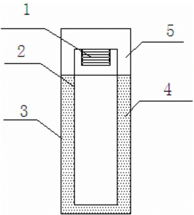
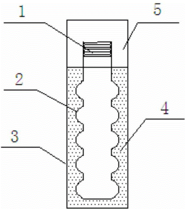
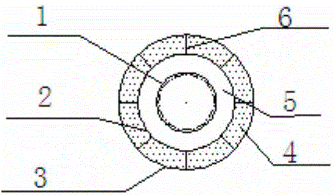
[0026] A phase-change temperature-regulating cup comprises a cup body shell, an inner cup shell, and a top cover, and a composite phase-change material is filled between the cup inner shell and the outer shell. The inner shell of the cup is selected from the inner shell of the corrugated structure. The ratio of the volume of the inner shell of the cup to the volume between the inner and outer shells is 1:1.15.

[0027] The composite phase change material includes a basic phase change material, a nucleating agent, a thermally conductive filler, and a thickening agent. The mass percentage of the basic phase change material is 75%, the addition amount of the nucleating agent is 5%, the addition amount of the thermally conductive filler is 20%, and the addition amount of the thickener is 0%. The basic phase change material is sodium sulfate decahydrate. The nucleating agent is borax. The thermally conductive filler is selected from two mixtures of graphite and carbon fiber, and...

Embodiment 2

[0029] A phase-change temperature-regulating cup comprises a cup body shell, an inner cup shell, and a top cover, and a composite phase-change material is filled between the cup inner shell and the outer shell. The inner shell of the cup adopts the inner shell of the tube outer fin structure. The ratio of the volume of the inner shell of the cup to the volume between the inner and outer shells is 1:1.1.

[0030] The composite phase change material includes a basic phase change material, a nucleating agent, a thermally conductive filler, and a thickening agent. The mass percentage of the basic phase change material is 95%, the addition amount of the nucleating agent is 0.5%, the addition amount of the thermally conductive filler is 3%, and the addition amount of the thickener is 1.5%. The basic phase change material is sodium carbonate decahydrate. Two kinds of nucleating agents are selected: strontium hydroxide octahydrate and strontium chloride hexahydrate, and the ratio is...

Embodiment 3

[0032] A phase-change temperature-regulating cup comprises a cup body shell, an inner cup shell, and a top cover, and a composite phase-change material is filled between the cup inner shell and the outer shell. The inner shell of the cup adopts the inner shell of the tube outer fin structure. The ratio of the volume of the inner shell of the cup to the volume between the inner and outer shells is 1:1.

[0033] The composite phase change material includes a basic phase change material, a nucleating agent, a thermally conductive filler, and a thickening agent. The mass percentage of the basic phase change material is 80%, the addition amount of the nucleating agent is 3%, the addition amount of the thermally conductive filler is 15%, and the addition amount of the thickener is 2%. The basic phase change material is selected from two mixtures of sodium acetate trihydrate and sodium thiosulfate pentahydrate in a ratio of 1:4. The nucleating agent is selected anhydrous disodium h...


PUM


Abstract

The invention relates to a phase transition temperature adjusting cup, which comprises a cup body outer casing, a cup body inner casing and a top cover, and the composite phase transition material is filled between the inner casing and the outer casing. The composite phase transition material comprises phase transition material, a nucleating agent, heat conduction filling material and a thickening agent. The phase transition material is selected from one or more of sodium acetate trihydrate, sodium thiosulfate pentahydrate, twelve disodium hydrogen phosphate, sodium sulfate decahydrate and decahydrate. <{EN4}>The nucleating agent is selected from one or more of borax, sodium phosphate dibasic anhydrous, diatomaceous earth, silica, sodium silicate, eight water strontium hydroxide, hexahydrate chloride strontium. <{EN5}>The heat conduction filling material is selected from one or more of graphite, carbon nanotube, expanded graphite, carbon fiber, graphene, three-dimensional graphite foam, silicon carbide, copper powder. <{EN6}>The thickening agent is selected from one of polyacrylic acid emulsion or carboxymethylcellulose sodium. <{EN7}>Compared with existing temperature adjusting cups, the phase transition temperature adjusting cup of the present invention has the advantages of rapid cooling, simple structure convenient operation, 3-4 hours of comfort temperature zone, and not being restricted from external environment.

Description


Claims


Application Information

Patent Timeline
Owner YUTIAN ENERGY CO LTD
Learn More