
Novel DIN connector

A connector, a new type of technology, applied in the direction of connection, contact parts, parts of the connection device, etc., can solve the problems of prolonged production cycle, unusable power divider, mismatched installation, etc., so as to reduce the difficulty of processing and assembly and improve production. Efficiency, cost reduction effects

Inactive Publication Date: 2015-09-09
HEFEI JIARUILIN ELECTRONICS TECH
View PDF3 Cites 1 Cited by
  • Summary
  • Abstract
  • Description
  • Claims
  • Application Information

AI Technical Summary

Problems solved by technology

[0002] The shell of the DIN type connector widely used at present is installed on the power divider cavity with 4 screws, and for the cavity power divider, due to the large demand for the N type cavity power divider, each manufacturer often It is designed and produced according to the requirements of N-type cavity power splitters. If a customer needs a DIN-type power splitter with the same frequency and power, the N-type shell and inner conductor will be different from the DIN-type power splitter due to the connector. The installation of the connector does not match, which makes the power divider unusable, so it is necessary to redesign and produce a new set of products suitable for DIN type connectors, which leads to a longer production cycle and increases the design workload of technicians. Moreover, the commonly used DIN type connector is installed on the cavity power divider. The shell must be very heavy and thick to be installed with 4 screws, resulting in the material cost of the shell being 3-4 times that of the N type. At the same time, the original DIN type The connector was originally designed and installed for the coupler, but it is difficult to install it on the power divider, and the price of the DIN connector is also very high, which seriously affects the popularization and use of the DIN connector power divider.

Method used


Image

  • Novel DIN connector

Examples


Embodiment Construction

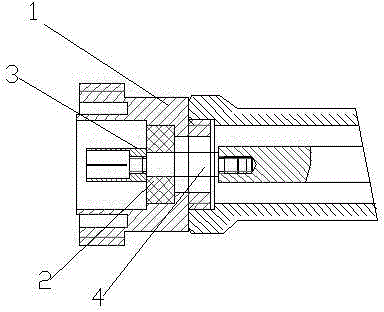
[0011] refer to figure 1 , a new type of DIN connector, which is composed of a shell 1, an insulator 2, a jack 3, and a pin 4. One end of the pin 4 is connected to the inner conductor of the power divider, and the other end is connected to the jack 3. An insulator 2 is installed between the two ends of the pin 4, and the shell 1 is installed on the outside of the insulator 2. The pin 4 and the socket 3 are two separate parts.

[0012] The stud at one end of the pin 4 is connected to the inner conductor screw hole of the power divider.

[0013] The stud at the other end of the pin 4 is internally threaded with the socket 3 .

[0014] The shell 1 is connected with the internal thread of the power divider through the external thread.

[0015] When installing the connector, screw the stud at one end of the pin into the screw hole of the inner conductor of the power divider, then screw the outer thread of the shell into the inner thread of the power divider, then install the insu...


PUM


Abstract

The invention relates to a novel DIN (German Industrial Standard) connector, belonging to the technical field of power dividers. The novel DIN type connector comprises an external shell, an insulator, a jack and a contact pin, wherein one end of the contact pin is connected with an inner conductor of a power divider, the other end of the contact pin is connected with the jack, the insulator is arranged between two ends of the contact pin, the external shell is installed outside the insulator, and the contact pin and the jack are separated. According to the novel DIN connector, the connection of the external shell of the connector and the inner conductor of the power divider is the same as that of the external shell of the connector and the N connector, and the tail is also of a DIN structure, so that the materials are greatly saved, and the cost is lowered; and the novel DIN connector has the greatest benefit that the shell of the N cavity power divider and the cavity are used universally, so that the difficulty in manufacture and assembling is lowered, and the production efficiency is improved.

Description

technical field [0001] The invention relates to the technical field of power dividers, in particular to a DIN type connector. Background technique [0002] The shell of the DIN type connector widely used at present is installed on the power divider cavity with 4 screws, and for the cavity power divider, due to the large demand for the N type cavity power divider, each manufacturer often It is designed and produced according to the requirements of N-type cavity power splitters. If a customer needs a DIN-type power splitter with the same frequency and power, the N-type shell and inner conductor will be different from the DIN-type power splitter due to the connector. The installation of the connector does not match, which makes the power divider unusable, so it is necessary to redesign and produce a new set of products suitable for DIN type connectors, which leads to a longer production cycle and increases the design workload of technicians. Moreover, the commonly used DIN ty...

Claims


Application Information

Patent Timeline
Patent Type & Authority Applications(China)
IPC IPC(8): H01R13/02H01R4/56H01R13/516
CPCH01R13/02H01R4/56H01R13/516
Inventor 岳朝风
Owner HEFEI JIARUILIN ELECTRONICS TECH
Learn More