Multifrequency phased array ultrasonic Doppler flow detection system and method

A Doppler flow and detection system technology, applied in the field of ultrasonic Doppler flow detection, can solve the problems of not considering the speed of sound, low flexibility in application, inconvenient installation and debugging, etc.

Inactive Publication Date: 2011-01-05
SOUTH CHINA UNIV OF TECH
View PDF4 Cites 56 Cited by
  • Summary
  • Abstract
  • Description
  • Claims
  • Application Information

AI Technical Summary

Problems solved by technology

[0012] First, once the beam direction is determined, it is difficult to modify or deflect it. It can only measure the flow velocity distribution in four fixed directions, and its flexibility is not high, which limits its application;
[0013] Second, to form a sufficiently narrow beam width, a large number of array elements need to be used, for example, to form A beamwidth of approximately 16 The total diameter of the array needs to be composed of approximately 800 array units, and it is not convenient to install and debug. It is only suitable for the study of large flow fields
In order to ensure that the beam pointing does not shift too seriously, it is necessary to limit the large change of the operating frequency during beam scanning, that is, to limit the bandwidth of the array
However, the narrowband signal pulse length is the reciprocal of its bandwidth, which limits the transmission bandwidth and also limits the shortest pulse length of the transmitted signal. However, in order to improve the distance resolution, the pulse length must be reduced, and there is a contradiction between the two;
[0016] Fifth, the system uses the sound velocity in water to calculate the flow velocity, and does not consider the influence of sound velocity changing with temperature, so it can only be applied to constant temperature water flow velocity measurement
Due to the lack of effective sound velocity compensation measures, when the sound velocity changes, the measurement results will have a large deviation

Method used


Image

  • Multifrequency phased array ultrasonic Doppler flow detection system and method
  • Multifrequency phased array ultrasonic Doppler flow detection system and method
  • Multifrequency phased array ultrasonic Doppler flow detection system and method

Examples


Embodiment Construction

[0087] The present invention will be further described in detail below in conjunction with the embodiments and the accompanying drawings, but the embodiments of the present invention are not limited thereto.

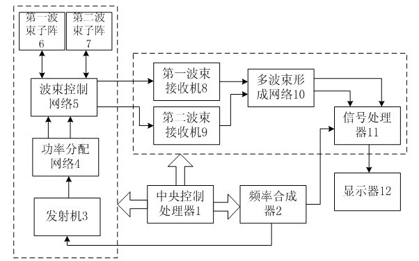
[0088] figure 1 The structure of the multi-frequency phased array ultrasonic Doppler flow detection system of the present invention is given, including a central control processor 1, a frequency synthesizer 2, a transmitter 3, a power distribution network 4, a beam control network 5, a first beam Sub-array 6 , second beam sub-array 7 , first beam receiver 8 , second beam receiver 9 , multi-beam forming network 10 , signal processor 11 , display 12 . The central control processor 1 communicates with the frequency synthesizer 2, the transmitter 3, the power distribution network 4, the beam control network 5, the first beam receiver 8, the second beam receiver 9, the multi-beam forming network 10, and the signal processor 11 respectively. 1. The display 12 is connected, wh...


PUM


Abstract

The invention discloses a multifrequency phased array ultrasonic Doppler flow detection system and a multifrequency phased array ultrasonic Doppler flow detection method. The system comprises a central control processor, a frequency synthesizer, a transmitting part, a receiving part and a display, wherein the transmitting part comprises a transmitter, a power distribution network, a beam control network, a first beam subarray and a second beam subarray; the receiving part comprises a first beam receiver, a second beam receiver, a multi-beam forming network and a signal processor. The system is characterized in that the central control processor is respectively connected with the frequency synthesizer, the transmitter, the power distribution network, the beam control network, the first beam receiver, the second beam receiver, the multi-beam forming network and the signal processor. In the detection method of the system, beam deflection and dynamic focusing are realized through the phased array technology, multi-directional and multi-depth positions can be measured on the cross section of an integral pipeline, and by a mode of adjusting beam scanning dynamically, the processing timeof the beam scanning is reduced, and the measuring accuracy is improved.

Description

technical field [0001] The invention relates to the technical field of ultrasonic Doppler flow detection, in particular to an ultrasonic Doppler flow detection system and method. Background technique [0002] The measurement principle of the ultrasonic Doppler flowmeter is based on the Doppler effect. According to the acoustic Doppler effect, when there is relative motion between the sound source and the observer, the frequency of the acoustic signal observed by the observer will be different. For the frequency emitted by the sound source, the frequency change caused by relative motion is proportional to the relative speed of the two objects. In the ultrasonic Doppler flow measurement method, the ultrasonic transmitting transducer is a fixed sound source, which transmits a fixed frequency acoustic signal into the measured fluid, and the suspended particles or bubbles moving with the fluid reflect the transmitted ultrasonic wave back to the receiver. transducer. The relativ...

Claims


Application Information

Patent Timeline
Patent Type & Authority Applications(China)
IPC IPC(8): G01F1/66
Inventor 韦岗刘逸豪曹燕陈庭柱宁更新张军
Owner SOUTH CHINA UNIV OF TECH
Why Eureka
Try Eureka