Contact Lens and Method of Producing Contact Lens

a technology of contact lens and contact lens, which is applied in the field of contact lens, can solve the problems of reducing productivity, difficulty in maintaining satisfactory water retentivity for an extended period, and reducing water retentivity, so as to achieve high-quality oscillation control, reduce production costs, and produce efficient minute periodic structures

Inactive Publication Date: 2009-12-10
MENICON CO LTD
View PDF11 Cites 58 Cited by
  • Summary
  • Abstract
  • Description
  • Claims
  • Application Information

AI Technical Summary

Benefits of technology

[0010]With the foregoing in view, it is accordingly one object of the present invention to provide a contact lens of novel structure that can be produced at enhanced production efficiency, and that has enhanced water retentivity on the lens surface so as to realize a superior wear feeling.

Problems solved by technology

However, an inherent problem with the contact lens disclosed in Patent Citation 1 is that the hydrophilic groups present on the lens surface tend to rotate within the molecule and to become hidden inside the resin of the lens, so that hydrophilicity is lost within a relatively short time, thus making it difficult for satisfactory water retentivity to be maintained for an extended period.
Moreover, it requires subjecting each contact lens to plasma treatment, resulting in the problem of diminished productivity.
However, a problem with these contact lenses is that the hydrophilic coating present on the surface tends to peel off with repeated rubbing during cleaning, resulting in a drop in water retentivity.
Also, during production of the contact lenses, in addition to plasma treatment carried out analogously to Patent Citation 1 there is further required a step to immerse the lens in the hydrophilic monomer and to polymerize the monomer; and a subsequent step to remove unwanted matter such as unreacted monomer and by-product polymers, creating the problem of further reduction in production efficiency.
It is furthermore difficult to adequately control the thickness of the hydrophilic coating which forms on the surface, resulting in localized variations in water retentivity on the lens surface, as well as in variability in water retentivity among lenses, making it difficult to assure a high level of product quality.

Method used


Image

  • Contact Lens and Method of Producing Contact Lens
  • Contact Lens and Method of Producing Contact Lens
  • Contact Lens and Method of Producing Contact Lens

Examples


examples

[0115]A series of tests carried out for the purpose of demonstrating the technological advantages afforded by the contact lens and the contact lens production method in accordance with the present invention are presented below by way of examples.

[0116]First, a die plate of material comparable to that of the female mold molding die 32 (second die 46) that is employed in production of the contact lens 10 according the preceding embodiment was prepared. The material of the die plate was STAVAX™.

[0117]Next, laser light was directed onto the surface of the die plate to produce a minute periodic structure. As the laser light, there was employed a femtosecond laser with wavelength of 800 nm, pulse width of 120 fs, and repetition frequency of 1 kHz. A femtosecond laser machining unit made by Canon Machinery Co. Ltd. was used as the femtosecond laser machining unit.

[0118]A resin plate of material comparable to that of the lens molding female mold 36 in the preceding embodiment and correspond...


PUM

PropertyMeasurementUnit
depthaaaaaaaaaa
depthaaaaaaaaaa
aspect ratioaaaaaaaaaa

Abstract

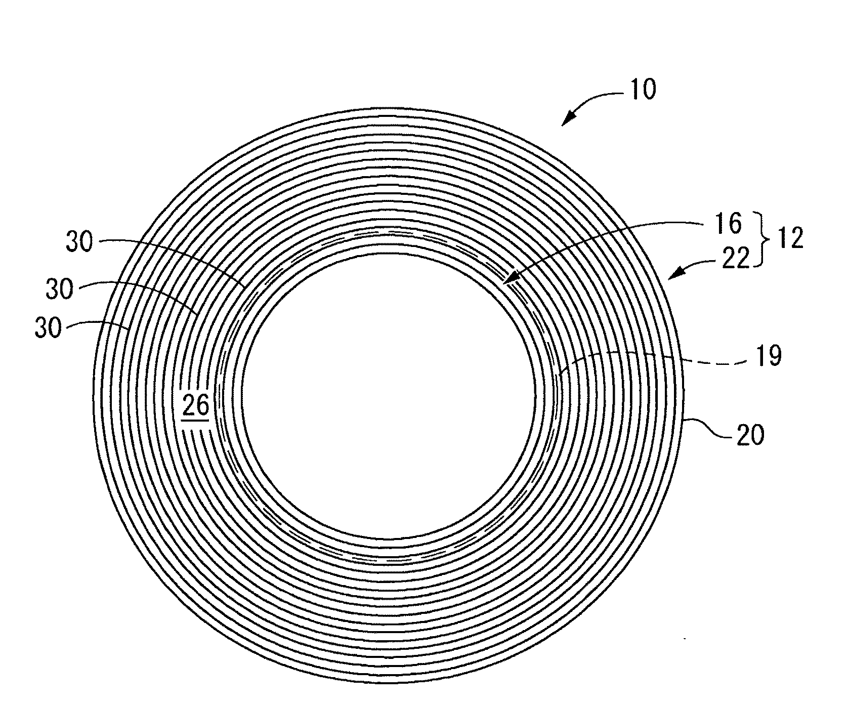
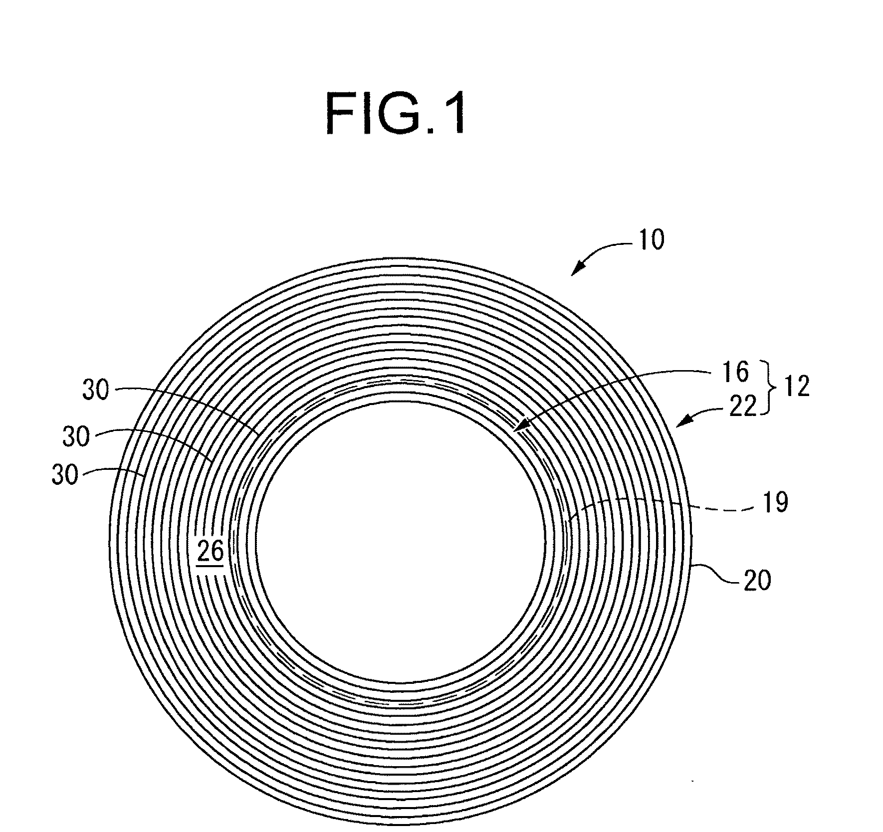
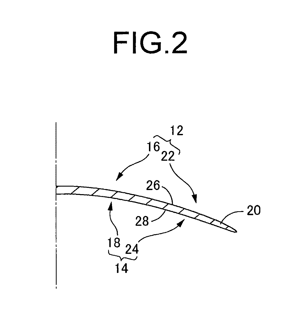
A contact lens of novel structure that can be produced with enhanced production efficiency and that has an enhanced water retainability on the lens surface so as to realize a superior wear feeling. At least one of convex lens anterior surface (12) and concave lens posterior surface (14) is provided with treated face (26, 28) having a periodic structure of minute projections and depressions of a size producing no tactile and visual effects during wear.

Description

TECHNICAL FIELD[0001]The present invention relates to a contact lens of soft type, hard type, or a type that combines elements of these; and relates in particular to a contact lens of novel structure affording superior wear feeling, and to a method of producing such a contact lens.BACKGROUND ART[0002]In the field of contact lenses of soft type, hard type, and types that combine elements of these (hereinafter referred to generally as “contact lenses”), it is well known that excellent water retentivity on lens surfaces will have the effect of enhancing wetted feel and improving wear feeling. Specifically, the presence of lacrimal fluid on the anterior surface of a contact lens will have the effect of reducing the foreign body sensation by providing smoother contact with the eyelid during blinking, as well as affording uniform wetting of the lens surface, which aids in viewing objects more clearly as well. The presence of lacrimal fluid on the lens posterior surface also has the effect...

Claims


Application Information

Patent Timeline
Patent Type & Authority Applications(United States)
IPC IPC(8): G02C7/04B29D11/00
CPCB29C33/40B29C33/424G02C7/04B29D11/00125B29D11/00346B29C45/372B29D11/00038B29D11/0049
Inventor SUZUKI, HIROAKIKOBAYASHI, ATSUSHI
Owner MENICON CO LTD
Why Eureka
Try Eureka