Wing aerodynamics modeling method

A dynamic modeling, wing technology, applied in special data processing applications, instruments, electrical digital data processing, etc. question

Active Publication Date: 2015-09-23
XIAN AIRCRAFT DESIGN INST OF AVIATION IND OF CHINA
View PDF4 Cites 21 Cited by
  • Summary
  • Abstract
  • Description
  • Claims
  • Application Information

AI Technical Summary

Problems solved by technology

[0002] In the initial stage of aircraft design, to evaluate the dynamic characteristics of the wing, it is necessary to establish a dynamic finite element model of the wing. However, the structural layout of the wing is not yet clear,

Method used


Image

  • Wing aerodynamics modeling method
  • Wing aerodynamics modeling method

Examples


Embodiment Construction

[0028] Reference will now be made in detail to the exemplary embodiments, examples of which are illustrated in the accompanying drawings. When the following description refers to the accompanying drawings, the same numerals in different drawings refer to the same or similar elements unless otherwise indicated.

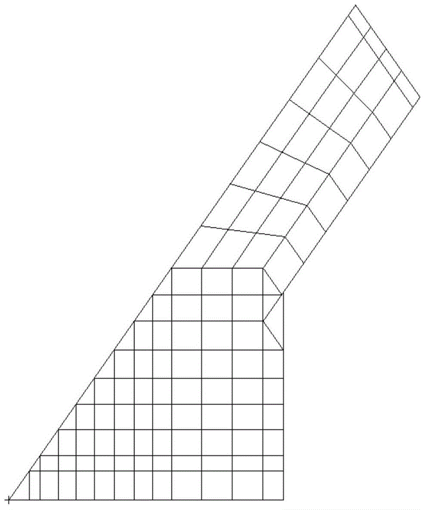
[0029] like figure 1 As shown, a kind of wing dynamics modeling method provided by the present invention comprises the following steps:

[0030] Step 1. Establish a structural grid for flow field analysis according to the initially given wing shape layout, and calculate its steady flow field result, wherein the steady flow field result includes the pressure on the upper and lower surfaces of the wing. Further, in this embodiment, the structural grid used for flow field analysis is established by CFD software, and the steady flow field result is obtained through calculation.

[0031] Step 2. Establish a pure sheet element finite element model of the wing, specify an i...


PUM


Abstract

The invention relates to the field of aeroelasticity, in particular to a wing aerodynamics modeling method. The airplane stiffness and mass distribution can be obtained in the early airplane design period under the condition of undefined wing structure arrangement. According to the wing aerodynamics modeling method provided by the invention, firstly, a finite element model of a wing pure metal plate element is built; the obtained aerodynamic lift is calculated; then, the thickness of the metal plate element is used as a variable, the wing tip deformation, the gravity center, the modal frequency, the flutter speed and the like are used as constraint conditions, and the wing weight is used as an optimization objective; finally, a group of metal plate element thickness distribution values is obtained through optimization calculation, so that the airplane stiffness and mass distribution is simulated; and the wing stiffness and mass distribution can be fast obtained in the early airplane design period under the conditions that the wing structure arrangement is not clear and only the wing pneumatic appearance and the weight are known, so that the wing aerodynamics feature analysis is carried out.

Description

technical field [0001] The invention relates to the field of aeroelasticity, in particular to a wing dynamics modeling method. Background technique [0002] In the initial stage of aircraft design, to evaluate the dynamic characteristics of the wing, it is necessary to establish a dynamic finite element model of the wing. However, the structural layout of the wing is not yet clear, and there are only conceptual data such as aerodynamic shape, weight, and center of gravity. The stiffness and mass distribution of the wing make it difficult to establish a dynamic finite element model of the wing through conventional modeling methods. Contents of the invention [0003] The purpose of the present invention is to provide a wing dynamics modeling method, which can obtain the stiffness and mass distribution of the aircraft in the early stage of aircraft design when the structure layout of the wing is not yet clear. [0004] Technical scheme of the present invention is: [0005] ...

Claims


Application Information

Patent Timeline
IPC IPC(8): G06F17/50
Inventor 陈海郭润江龚亮孙晓红张红波
Owner XIAN AIRCRAFT DESIGN INST OF AVIATION IND OF CHINA
Why Eureka
Try Eureka