Slagging device and circulating fluidized bed boiler

A slag dropping and boiler technology, which is applied in the fields of slag dropping devices and circulating fluidized bed boilers, can solve the problems of interruption of slag discharge pipelines, reduction of materials in the furnace, destruction of cold slag slag discharge devices, etc., and achieves reliable operation and easy wind speed. control effect

Active Publication Date: 2017-09-15
CHINA SHENHUA ENERGY CO LTD +2
View PDF4 Cites 0 Cited by
  • Summary
  • Abstract
  • Description
  • Claims
  • Application Information

AI Technical Summary

Problems solved by technology

This part of the gas in the slag cooler will fluidize and lubricate the transportation of the particles, so that the particles cannot form an effective accumulation at the inlet of the slag cooler, and its flow in the slag cooler is no longer controlled by the drum. The ribs are controlled, so the drum will lose control of the slag discharge, which is the phenomenon of slag flow
When the slag flow occurs in the slag cooler, the flow rate of the bottom slag will be out of control, and a large amount of materials in the furnace will enter the slag cooler in a short period of time, which will damage the slag cooling and slag discharge devices, reduce the materials in the furnace, and lower the bed temperature. In severe cases, it may lead to shutdown
[0004] The current method of controlling slag flow is often to close the inlet opening of the slag falling device, for example, by figure 1 The opening of the valve 8 is adjusted, but this method often brings about the problem of slag blocking, and the slag discharge is easily interrupted because the pipeline opening is too small
After the occurrence of slag blockage, it is usually necessary to restore the slag discharge by manual slag removal, which will bring high labor costs, so this method is not an ideal method to solve the problem of slag flow in the slag cooler

Method used


Image

  • Slagging device and circulating fluidized bed boiler
  • Slagging device and circulating fluidized bed boiler

Examples


Embodiment Construction

[0027] Specific embodiments of the present invention will be described in detail below in conjunction with the accompanying drawings. It should be understood that the specific embodiments described here are only used to illustrate and explain the present invention, and are not intended to limit the present invention.

[0028] In the description of the present invention, it should be noted that the orientation or positional relationship indicated by the terms "upper" and "lower" is based on the orientation or positional relationship shown in the drawings, and is only for the convenience of describing the present invention and simplifying the description. It is not intended to indicate or imply that the referred device or element must have a particular orientation, be constructed in a particular orientation, and operate in a particular orientation, and thus should not be construed as limiting the invention.

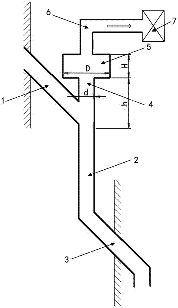
[0029] The invention provides a slagging device, the slagging device i...


PUM


Abstract

The invention discloses a slag falling device and a circulating fluidized-bed boiler. The slag-falling device comprises a slag discharging pipe (1), a conveying pipe (2) and a slag feeding pipe (3), wherein an upper end port of the slag discharging pipe (1) is communicated with a slag discharging port of the boiler, and a lower end port of the slag discharging pipe (1) is communicated with an upper end port of the conveying pipe (2); and an upper end port of the slag feeding pipe (3) is communicated with a lower end port of the conveying pipe (2), and a lower end port of the slag feeding pipe (3) is communicated with a slag feeding port of a slag cooler. The slag falling device also comprises an air inducing component which is communicated with the conveying pipe (2) and can form a low-pressure zone above the conveying pipe (2). The air inducing component forms the low-pressure zone above the conveying pipe, so that the gas flow which is carried into the slag cooler by bottom slag when the bottom slag flows downwards is reduced, and a slag running phenomenon caused by lubrication and fluidization effects of gases is avoided; and at the same time, gases entering the low-pressure zone flow in a single phase, so that the wind volume and the wind speed are easy to control.

Description

technical field [0001] The invention relates to the field of boiler slagging, in particular to a slagging device and a circulating fluidized bed boiler. Background technique [0002] my country has abundant inferior fuel reserves, and circulating fluidized bed boilers have wide adaptability to coal types. The low-cost and high-efficiency utilization of inferior fuels can be realized through circulating fluidized bed boiler combustion technology. The common characteristics of low-quality fuels are low calorific value and high ash content. Therefore, circulating fluidized bed boilers burning these fuels have a large flow of fly ash and a very large flow of bottom slag. In order to control bed pressure and bed thickness, prevent slag deposition, ensure good fluidization conditions, stabilize combustion, and avoid ash and slag coking, these bottom slags must be discharged in a timely manner. On the other hand, the heat transfer, mass transfer, and combustion in the circulating ...

Claims


Application Information

Patent Timeline
Patent Type & Authority Patents(China)
IPC IPC(8): F23C10/24
CPCF23C10/24F23C2206/10
Inventor 曹培庆刘小奇白杨赵勇纲汪佩宁吕俊复刘青张缦
Owner CHINA SHENHUA ENERGY CO LTD
Why Eureka
Try Eureka