Rotatable orifice plate for direct flow measurement

A flow measurement, orifice plate technology, applied in the detection of fluid flow by measuring differential pressure, volume/mass flow generated by mechanical effects, valve devices, etc., can solve problems such as occupying space and increasing head loss in pressure-related systems

Active Publication Date: 2019-09-24
FLUID HANDLING
View PDF6 Cites 0 Cited by
  • Summary
  • Abstract
  • Description
  • Claims
  • Application Information

AI Technical Summary

Problems solved by technology

These additional components in the system take up additional space and increase the head loss of the pressure dependent system
Depending on the type of flow measuring device being used, a significant amount of additional pipe length may be required

Method used


Image

  • Rotatable orifice plate for direct flow measurement
  • Rotatable orifice plate for direct flow measurement
  • Rotatable orifice plate for direct flow measurement

Examples


Embodiment Construction

[0049] Figure 1 to Figure 7

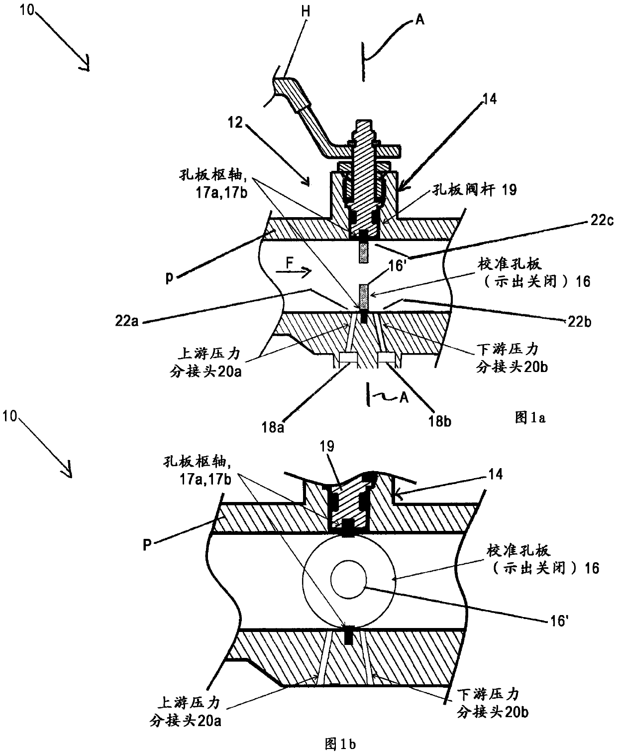
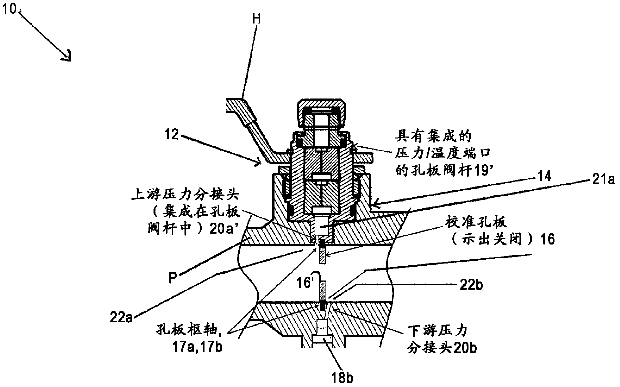
[0050] under normal circumstances, figure 1 with Figure 3-7 Both show a cross-sectional view of a device indicated as a whole at 10, the device having a valve indicated as a whole at 12, the valve has a valve body or housing indicated as a whole at 14, which is configured to be arranged in a pipe with a fluid flow F P may form part of the pipeline.

[0051] in figure 1 with Figure 3-7 In this case, the valve body or housing 14 is configured to have at least one pressure tap 20a, 20b arranged at at least one position 22a, 22b along the pipe P to allow the pressure of the fluid flow F of the pipe P to be measured .

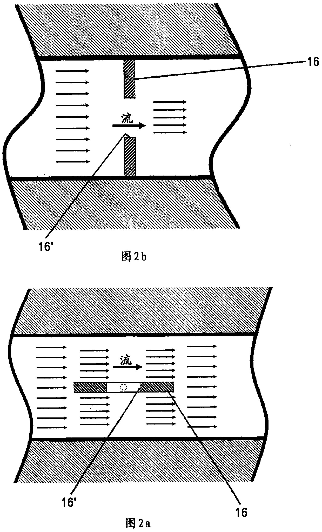
[0052] For example, in figure 1 In this case, the valve 12 includes an orifice plate 16 having an opening 16' and configured to be in the valve body or valve housing 14, for example about the orifice plate pivots 17a, 17b as shown, rotating about the axis of rotation A, the axis A Positioned at a position 22c different from the at leas...


PUM


Abstract

A valve is provided having a valve housing / valve body that may be configured to be disposed within a conduit having a fluid flow, or form part of a conduit, and configured to have a valve disposed along a conduit having a fluid flow. The pressure tap of the pipe is positioned to allow the pressure of the fluid flow of the pipe to be measured; and the valve also has a rotatable orifice plate configured within the valve body or valve housing. Rotating about the axis of rotation, the rotatable orifice plate is positioned along the pipe at a different position than the pressure tap for a first rotatable position providing normal fluid flow operation and providing a basis for direct flow measurement of the fluid flow. rotating between a second rotatable position perpendicular to the fluid flow, wherein when the orifice plate is in the second rotatable position, the direct flow measurement of the fluid flow is based on the flow rate sensed by the pressure tap sensor, A signal containing information about the measured pressure at the pressure tap is determined.

Description

[0001] Cross references to related applications [0002] This application claims the rights and interests of the provisional application serial number 61 / 756814 (the agent file number F-B&G-X0006 / / 911-19.8-1) filed on January 25, 2013, which is incorporated herein by reference in its entirety. [0003] This application is also a part of the continuation application of the serial number 13 / 681628 (agent file number F-B&G-X0003 / / 911-19.6-1) filed on November 20, 2012, and claims its rights and interests, which are quoted as a whole Incorporated into this article. Technical field [0004] The present invention relates to a technique for providing direct flow measurement; and more specifically, the present invention relates to a valve configured to provide direct flow measurement. Background technique [0005] Currently, most known systems where fluids flow at a constant rate require a separate permanent flow measurement device to verify the flow rate of the system. These additional com...

Claims


Application Information

Patent Timeline
Patent Type & Authority Patents(China)
IPC IPC(8): G01F1/36
CPCG01F1/42F16K1/222
Inventor S·P·小埃文斯F·罗斯卡M·奈尔G·维勒卡
Owner FLUID HANDLING
Why Eureka
Try Eureka