A multi-plane collimated energy-dissipating shock absorber

A collimation and shock absorber technology, which is applied in the direction of shock resistance and building components, can solve the problems of shock absorption effect, self-heaviness, deformation instability, etc., and achieve the effect of wide application range, strong absorption capacity and reasonable design

Inactive Publication Date: 2018-03-13
EAST CHINA UNIV OF TECH
View PDF4 Cites 0 Cited by
  • Summary
  • Abstract
  • Description
  • Claims
  • Application Information

AI Technical Summary

Problems solved by technology

The main problems or defects existing in the existing energy dissipation shock absorber: 1) The non-energy-consuming support parts are mostly shaped steel, which has a large dead weight, a large additional bearing capacity to the main structure, and high cost. In addition, due to the axial The pressure is generated, so the influence of the buckling problem needs to be considered, which brings great troubles to the design; 2) The yield deformation of the metal component is used as the energy-dissipating part, the deformation is relatively unstable, and there is slippage, which has a great impact on the energy-dissipating capacity ; 3) The energy dissipation and shock absorption effects are only good for one-way, but the randomness of the earthquake leads to uncertainty in the input direction of the seismic wave
In this way, the shock absorption effect of the current energy dissipation shock absorber on the overall structure will be affected to varying degrees

Method used


Image

  • A multi-plane collimated energy-dissipating shock absorber
  • A multi-plane collimated energy-dissipating shock absorber
  • A multi-plane collimated energy-dissipating shock absorber

Examples


Embodiment Construction

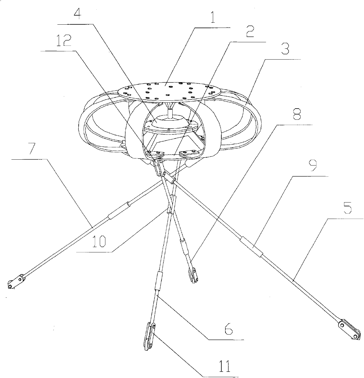
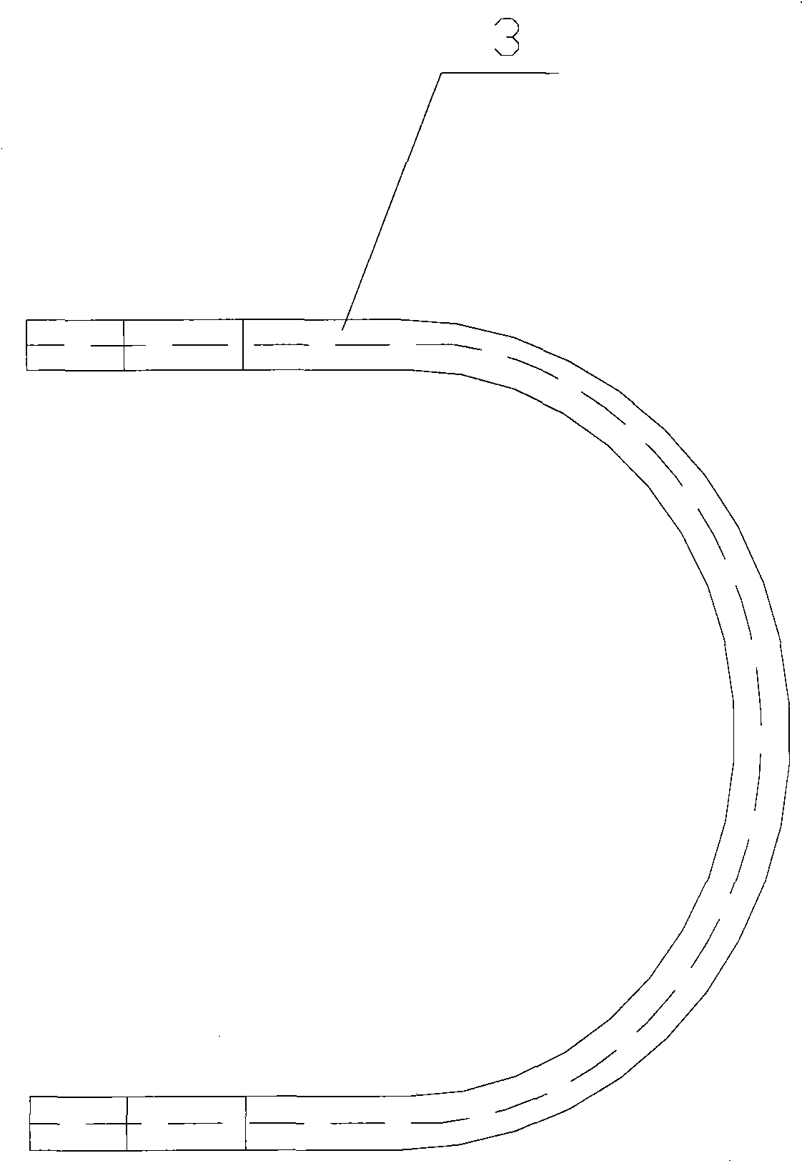
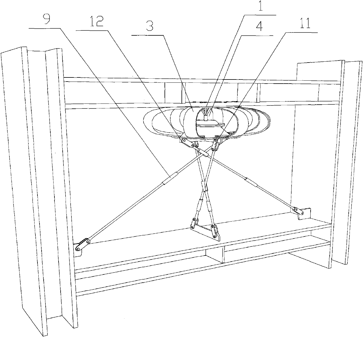
[0012] Such as Figure 1-Figure 3 As shown, the specific embodiment adopts the following technical scheme: it includes upper steel plate 1, lower steel plate 2, U-shaped steel plate energy dissipation damping 3, ball hinge 4, first steel round bar 5, second steel round bar 6, third Steel round bar 7, fourth steel round bar 8, steel cylinder with internal thread 9, hollow steel round bar 10, hinged steel plate 11, stiffening rib 12, upper steel plate 1 and lower steel plate 2 are connected by ball hinge 4 to form a rotating fixture , several U-shaped steel plate energy dissipation dampers 3 are evenly distributed in the fixture, the upper part of the lower steel plate 2 is provided with a hinge member, the lower part of the lower steel plate 2 is provided with a stiffener 12, the first steel round bar 5, the second steel round bar 6 , the third steel round bar 7 and the fourth steel round bar 8 are intersected, wherein the intersection of the second steel round bar 6 and the fo...


PUM


Abstract

The invention discloses a multi-plane quasi-linear energy-dissipating shock absorber, which relates to the technical field of energy-dissipating and shock-absorbing structures in civil engineering. A hollow steel round bar is arranged at the intersection of the second steel round bar and the fourth steel round bar , the hollow steel round bar is installed on the second steel round bar, the two ends of the first steel round bar, the second steel round bar, the third steel round bar and the fourth steel round bar are all provided with hinged steel plates, and the first steel round bar The upper ends of the round bar, the second steel round bar, the third steel round bar and the fourth steel round bar are all installed on the stiffener at the lower part of the lower steel plate through the hinged steel plate, and the first steel round bar, the second steel round bar, the third steel round bar Both the round bar and the fourth steel round bar are sheathed with a steel cylinder with internal threads. Compared with the existing energy-dissipating damping and shock-absorbing structures, it has light weight, strong absorption capacity, and is relatively stable, and has energy-dissipating and shock-absorbing functions for seismic waves in any direction, and has multi-directional and omni-directional energy-dissipating and shock-absorbing functions , can be applied to various large-span space structures, with reasonable design, simple structure and wide application range.

Description

Technical field: [0001] The invention relates to a multi-plane quasi-linear energy-dissipating shock absorber, which belongs to the technical field of energy-dissipating and shock-absorbing structures in civil engineering. Background technique: [0002] The main components of existing energy dissipation and shock absorbing devices are divided into two parts: support components and energy dissipation components. The support components are mostly heavy-duty structures such as section steel; Deformation and axial tension and compression deformation. The main problems or defects existing in the existing energy dissipation shock absorber: 1) The non-energy-consuming support parts are mostly shaped steel, which has a large dead weight, a large additional bearing capacity to the main structure, and high cost. In addition, due to the axial The pressure is generated, so the influence of the buckling problem needs to be considered, which brings great troubles to the design; 2) The yi...

Claims


Application Information

Patent Timeline
Patent Type & Authority Patents(China)
IPC IPC(8): E04B1/98
Inventor 高金贺昌毅邵炜星林斯任
Owner EAST CHINA UNIV OF TECH
Why Eureka
Try Eureka