Steel wire rope damping shock absorption expansion joint and bridge
A technology for steel wire ropes and expansion joints, applied in bridges, bridge parts, bridge construction, etc., can solve limited and other problems, and achieve the effects of flexible movement, novel structure, and convenient installation and maintenance
- Summary
- Abstract
- Description
- Claims
- Application Information
AI Technical Summary
Problems solved by technology
Method used
Image
Examples
Embodiment 1
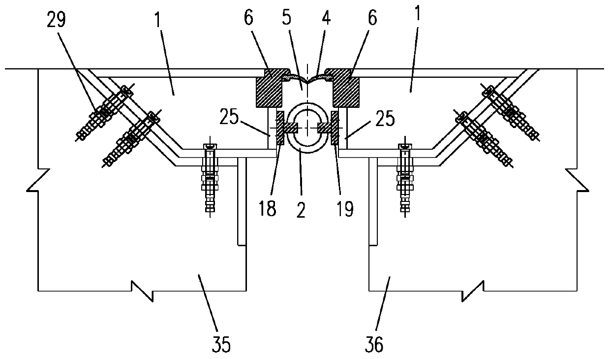
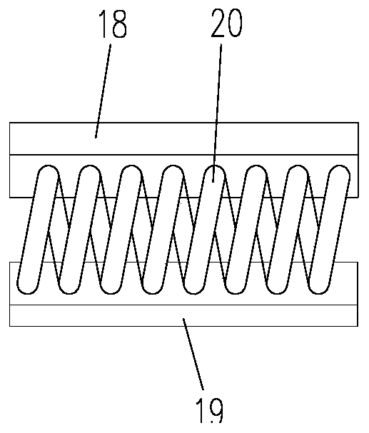
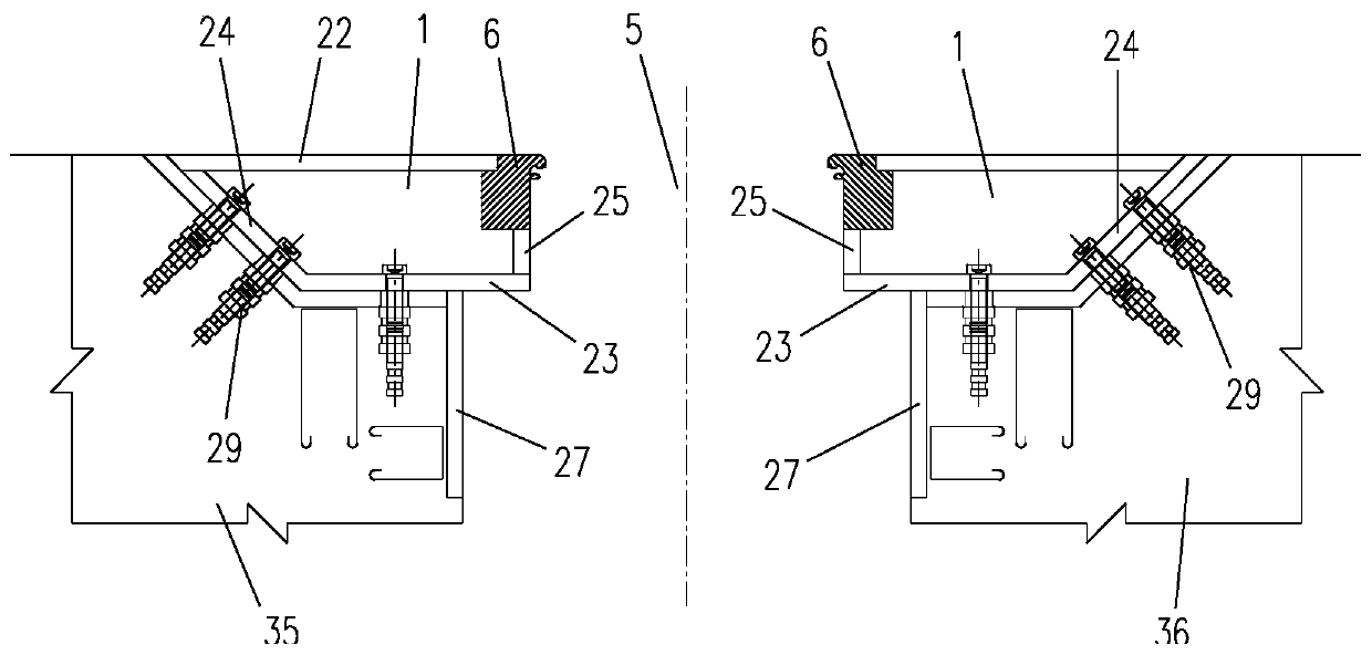
[0043] Such as Figure 1-4 As shown, the present invention provides a steel wire rope damping shock-absorbing expansion joint, including a wire rope damper 2 and two anchor structures 1 symmetrically arranged, the steel wire damper 2 is fixed between the two anchor structures 1, and the two A side longitudinal beam 6 is arranged on the top edge of the opposite side of the anchor structure 1, and a waterproof structure is arranged between the two side longitudinal beams 6. The wire rope damper 2 and the side longitudinal beam 6 are all parallel to the side wall of the anchor structure 1 (i.e. Baffle plate 25) arrangement.
[0044]The invention adopts the steel wire rope damper as the energy dissipation member, so that the expansion joint has the function of energy dissipation and shock absorption, and the structure is simple; the supporting system of the single joint only has side beams and no middle beams, so scissors bracing is not needed, and the two side longitudinal beams ...
Embodiment 2
[0050] Such as Figure 5-10 As shown, in order to adapt to the gap size of different expansion joints and improve the structural bearing capacity and shock absorption effect, on the basis of Embodiment 1, the steel wire rope damping shock absorption expansion joint of the present invention can also include a top layer fixed between two anchor structures Scissors support system 3, the top scissors support system 3 includes one or more middle longitudinal beams 7, bottom beams 8, sliders 9 and two rows of scissors structures 10, the two rows of scissors structures 10 are symmetrically distributed on At the two ends of the middle longitudinal beam 7, the wire rope damper 2 is not directly connected to the anchor structure, but is installed between the two rows of scissor brace structures 10, and a plurality of scissor brace structures 10 are arranged at the top and side vertically. The beam 6 is connected to one end of the middle longitudinal beam 7, and the bottom of the scissor...
Embodiment 3
[0056] Such as Figure 11 As shown, when the beam body or building structure is relatively thick, that is, when the expansion joint depth is relatively deep, on the basis of Embodiment 2, a bottom scissors support system 15 can also be set, and the bottom scissors support system 15 is The direction is arranged below the top scissors support system 3, and one or more wire rope dampers are arranged in the bottom scissors support system 15, and the bottom scissors support system includes a slide block and two rows of scissors structures (not shown in the figure). Specifically shown), the slider and the two rows of scissor brace structures are the same as those in the top scissor brace support system, and the scissor brace structure of the bottom scissor brace support system and the scissor brace structure of the top scissor brace support system pass through the shared bottom beam It is connected with the slide block, and the bottoms of the adjacent scissor supports in each row of...
PUM
 Abstract
Description
Claims
Application Information
 - R&D
- Intellectual Property
- Life Sciences
- Materials
- Tech Scout
- Unparalleled Data Quality
- Higher Quality Content
- 60% Fewer Hallucinations
Browse by: Latest US Patents, China's latest patents, Technical Efficacy Thesaurus, Application Domain, Technology Topic, Popular Technical Reports.
© 2025 PatSnap. All rights reserved.Legal|Privacy policy|Modern Slavery Act Transparency Statement|Sitemap|About US| Contact US: help@patsnap.com


