Realization method of stereoscopic spherical-screen projection system

A technology of projection system and implementation method, applied in stereo photography, wide-screen photography, photography, etc., can solve the problems of high pixel loss, cannot be easily separated, and affect the viewing effect, so as to ensure the clarity and brightness, and increase the venue. Utilization, the effect of optimizing the seating arrangement

Active Publication Date: 2015-10-14
SHANGHAI HUABO INFORMATION SERVICE
View PDF8 Cites 12 Cited by
  • Summary
  • Abstract
  • Description
  • Claims
  • Application Information

AI Technical Summary

Problems solved by technology

[0002] The projectors of the existing dome projection system are mostly implemented with fisheye lenses, which requires the projector to be installed at the center of the dome, but this will lose the best viewing position for the audience and affect the viewing effect
Moreover, the fisheye lens itself deforms the picture greatly, and the pixel loss is high. When it is applied to a large dome screen, the clarity and brightness cannot achieve good results.
At the same time, the existing dome projection system does not have the function of stereoscopic projection and cannot project stereoscopic films. With the rapid development of film projection technology, audiences are increasingly demanding for large-view stereoscopic films. A dome theater that provides a three-dimensional, perfect visual experience appears
In terms of stereoscopic projection technology, due to its low cost and easy implementation, polarized passive stereoscopic technology is mostly used in theaters, but polarized passive stereoscopic technology mainly uses the direction of light to separate the left and right eye images, while the spherical screen itself The direction of light reflection and refraction is more complicated and cannot be separated simply

Method used


Image

  • Realization method of stereoscopic spherical-screen projection system
  • Realization method of stereoscopic spherical-screen projection system
  • Realization method of stereoscopic spherical-screen projection system

Examples


Embodiment

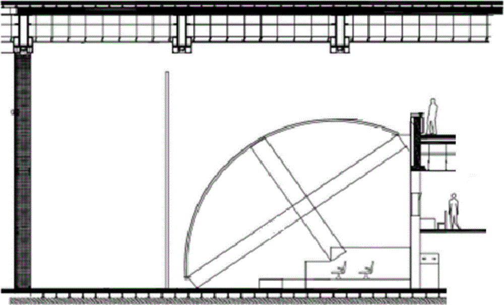
[0030] A three-dimensional spherical screen projection system comprises a spherical screen body 1, a background computer, a computer array, 10 projectors and a bracket. All projectors adopt lenses with standard focal lengths and are installed on the bracket. The computer array is composed of five computers with dual graphics cards. The background computer uses software to realize the communication and connection between the computer arrays, to realize the selection and synchronous projection of films of each channel, as well as the projectors of the cinema itself, the switch and control of computer equipment. Switching, switching and switching of lights.

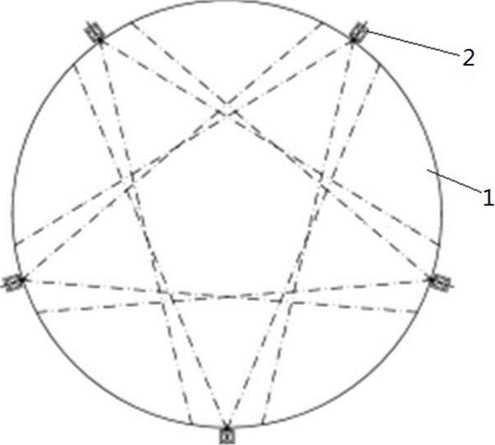
[0031] Such as figure 1 As shown, the spherical curtain body 1 selected in this embodiment is a structural design of 1 / 4 spherical canopy installed at 30 degrees.

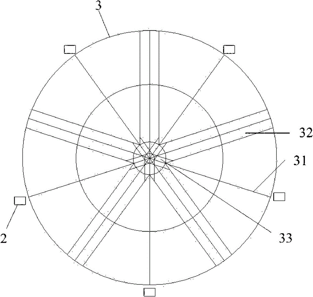
[0032] Such as figure 2 Shown, a kind of realization method of three-dimensional dome projection system comprises the following steps:

[0033] 1) Five proje...


PUM


Abstract

The invention relates to a realization method of a stereoscopic spherical-screen projection system. The method comprises the following steps: 1) arranging a plurality of projection channels at the edge of a spherical screen body, wherein each projection channel is provided with two projectors; 2) generating a mesh model with a computer based on spherical screen curved surface, carrying out fan-shaped segmentation on the mesh model according to the number and position of the projection channels, and selecting an effective fan-shaped area for each projection channel; 3) carrying out curved surface correction and edge fusion on each fan-shaped area; 4) adjusting the positions of the projectors and combining computer fusion fine tuning, and realizing left and right eye splicing of the projection channels to enable the projection picture of each projection channel to cover the spherical screen curved surface completely; and 5) carrying out synchronous output and synchronous projection on multichannel pictures. The realization method of the stereoscopic spherical-screen projection system is small in projection picture and small in picture pixel loss, and ensures definition and brightness of the pictures; and meanwhile, by enabling the adjacent cutting regions to form a regular fusion band, workload of the later-period correction work is greatly reduced.

Description

technical field [0001] The invention relates to a stereoscopic projection technology, in particular to a method for realizing a stereoscopic spherical screen projection system. Background technique [0002] The projectors of the existing dome projection system are mostly implemented with fisheye lenses, which requires the projector to be installed at the center of the dome, but in this way, the best viewing position for the audience will be lost and the viewing effect will be affected. Moreover, the fisheye lens itself deforms the picture greatly, and the pixel loss is high. When it is applied to a large dome screen, the clarity and brightness cannot achieve good results. At the same time, the existing dome projection system does not have the function of stereoscopic projection and cannot project stereoscopic films. With the rapid development of film projection technology, audiences are increasingly demanding for large-view stereoscopic films. A dome theater that provides a...

Claims


Application Information

Patent Timeline
Patent Type & Authority Applications(China)
IPC IPC(8): G03B35/20
CPCG03B35/20G03B37/00
Inventor 王薇和伟蒋莉莉周军明
Owner SHANGHAI HUABO INFORMATION SERVICE
Why Eureka
Try Eureka