Cylindrical workpiece engraving machine automatic clamp device

A technology of columnar workpieces and engraving machines, which is applied in the direction of engraving, positioning devices, metal processing machinery parts, etc., and can solve problems such as complex and changeable force and workpiece displacement

Active Publication Date: 2015-10-21
葆冈金属制品(珠海)有限公司
View PDF7 Cites 42 Cited by
  • Summary
  • Abstract
  • Description
  • Claims
  • Application Information

AI Technical Summary

Problems solved by technology

There are various types of engraving machines, including woodworking engraving machines, laser engraving machines, advertising engraving machines, jade engraving machines, stone engraving machines, etc. The engraving machine needs to clamp and position the workpiece during the engraving operation, such as the outer peripheral surface of the columnar workpiece. When engraving, the two ends of the columnar workpiece are usually fixed, but the engraving machine is different from the polishing machine or lathe. During the engraving process, the surface of the workpiece will be subjected to different directions and different sizes of force, that is, the force received is complex and changeable. If the clamping and positioning are only performed by the splint, the workpiece is prone to shift during the engraving process

Method used


Image

  • Cylindrical workpiece engraving machine automatic clamp device
  • Cylindrical workpiece engraving machine automatic clamp device
  • Cylindrical workpiece engraving machine automatic clamp device

Examples


Embodiment Construction

[0027] The following are specific embodiments of the present invention and in conjunction with the accompanying drawings, the technical solutions of the present invention are further described, but the present invention is not limited to these embodiments.

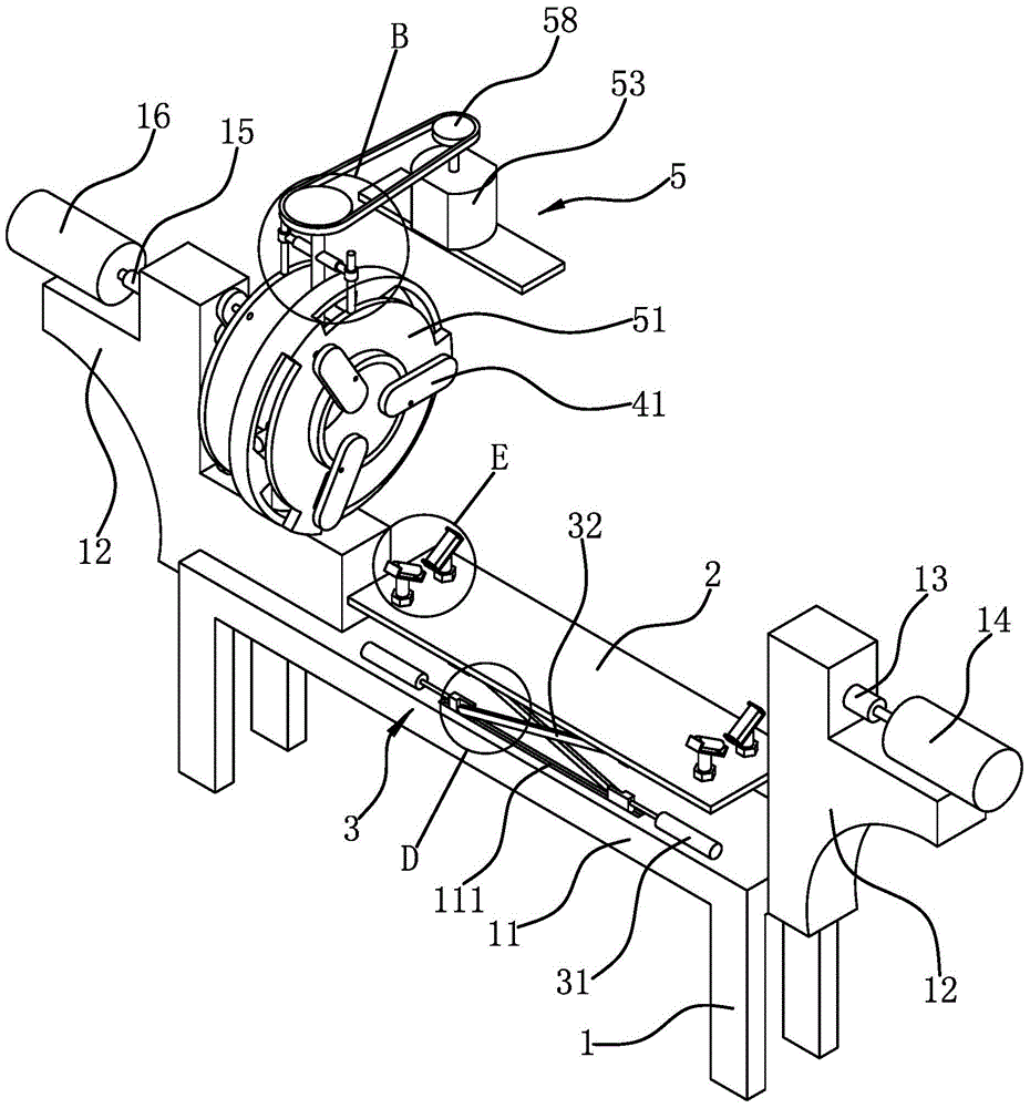
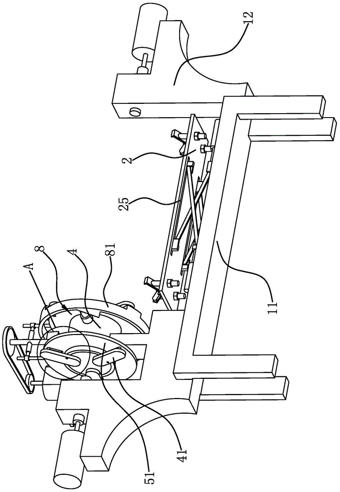
[0028] Such as figure 1 , figure 2 As shown, an automatic clamping device for a cylindrical workpiece engraving machine, the engraving machine includes a frame 1, a workbench 11 is provided on the frame 1, and an engraving machine head is provided on the frame 1 above the workbench 11, and the workbench 11 is horizontal A strip-shaped lifting plate 2 is provided, and two ends of the lifting plate 2 are provided with two guide wheels 21 for supporting columnar workpieces, and the axial directions of the guide wheels 21 are perpendicular to the length direction of the lifting plate 2, The workbench 11 is provided with a power part 3 capable of driving the lifting plate 2 to lift. The workbench 11 is slidably connected with...


PUM


Abstract

The invention provides a cylindrical workpiece engraving machine automatic clamp device, belongs to the machining equipment technical field, and solves the problems that an existing cylindrical workpiece cannot be stably clamped in engraving; the engraving machine comprises a frame having a work table; the work table is provided with a lifting plate, and fixedly connected with a positioning sleeve; two end edges of the positioning sleeve are respectively hinged to a plurality of positioning sheets; a pin shaft is arranged on one positioning face of the positioning sheet; the frame is provided with a drive piece; the positioning sleeve is connected with a plurality of supercharging columns in a radial direction in a slide manner; the supercharging columns are driven by the drive piece so as to abut against an outer circumferential wall of the cylindrical workpiece. The cylindrical workpiece engraving machine automatic clamp device can automatically clamp and position the cylindrical workpiece with high clamp precision and stability.

Description

technical field [0001] The invention belongs to the technical field of machining equipment, and relates to an automatic clamping device for a cylindrical workpiece engraving machine. Background technique [0002] Engraving is a combination of drilling and milling in terms of processing principle. The engraving machine has a wide range of applications. The low-power engraving machine is suitable for two-color boards, architectural models, small signs, three-dimensional crafts, etc., and the high-power engraving machine can be used for large-scale cutting and embossing. , engraving, etc. There are various types of engraving machines, including woodworking engraving machines, laser engraving machines, advertising engraving machines, jade engraving machines, stone engraving machines, etc. The engraving machine needs to clamp and position the workpiece during the engraving operation, such as the outer peripheral surface of the columnar workpiece. When engraving, the two ends of ...

Claims


Application Information

Patent Timeline
Patent Type & Authority Applications(China)
IPC IPC(8): B44B1/06B44B3/06B23Q3/06B23Q7/04B23K26/70
Inventor 郭嘉川
Owner 葆冈金属制品(珠海)有限公司
Why Eureka
Try Eureka