Cage part for a rolling bearing cage

A technology of rolling bearings and cages, applied in the direction of bearing components, rotating parts that resist centrifugal force, bearings, etc.

Inactive Publication Date: 2015-10-21
SCHAEFFLER TECH AG & CO KG
View PDF7 Cites 0 Cited by
  • Summary
  • Abstract
  • Description
  • Claims
  • Application Information

AI Technical Summary

Problems solved by technology

However, this solution has the disadvantage that, for guidance, the H-shaped middle part must be fastened with two additional side parts

Method used


Image

  • Cage part for a rolling bearing cage
  • Cage part for a rolling bearing cage
  • Cage part for a rolling bearing cage

Examples


Embodiment Construction

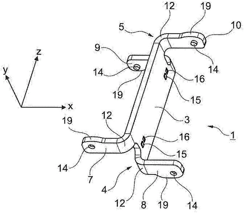
[0027] figure 1 The cage part 1 for a rolling bearing cage is shown in perspective. The illustrated cage part 1 is made of a sheet metal strip and comprises a web 3 extending in the longitudinal direction Z, at the ends of which a first support arm 4 and a second support arm 5 are arranged. The two support arms 4 , 5 each extend in a first transverse direction X perpendicular to the longitudinal direction Z and each comprise two half arms 7 , 8 or 9 , 10 bent opposite each other from the web 3 , which are are offset from each other in a second transverse direction Y perpendicular to the first transverse direction X and perpendicular to the longitudinal direction Z. The illustrated cage part 1 has an essentially H-shape. The half-arms 7 , 8 , 9 , 10 are produced by opposite bending of the separated ends of the metal strip.

[0028] The half-arms 7 , 9 and 8 , 10 of the opposite side arm 4 or 5 extending in the same direction are likewise offset from one another in the second...


PUM


Abstract

The invention relates to a cage part (1, 20, 40) for a rolling bearing cage (30), having a web (3) extending in a longitudinal direction (Z), at the ends of which a first supporting arm (4) and a second supporting arm (5) are arranged, each of which extends beyond the web (3) on both sides in a first transverse direction (X) perpendicular to the longitudinal direction (Z), wherein the supporting arms (4, 5) each comprise two half arms (7, 8, 9, 10) angled in the opposite direction to one another away from the web (3) and which are offset with respect to one another in a second transverse direction (Y) perpendicular to the first transverse direction (X) and the longitudinal direction (Z).

Description

technical field [0001] The invention relates to a cage part for a rolling bearing cage, with a web extending in the longitudinal direction, at the end of which a first support arm and a second support arm are arranged, each of which extends vertically A first transverse direction to the longitudinal direction extends beyond the tab on both sides. The invention also relates to a rolling bearing cage assembled from a plurality of the aforementioned cage parts. Background technique [0002] For large rolling bearings, it is known to insert so-called bolt cages as standard, for example in DE 10 2004 025 796 A1, in order to space and guide the rolling elements. The disadvantage is that a pin cage of this type can only be produced and assembled at a very high cost. Furthermore, the rolling elements must be drilled in the pin cage so that they are spaced apart by the pins. [0003] On the other hand, in order to keep the rolling elements at a distance in rolling bearings, it is ...

Claims


Application Information

Patent Timeline
Patent Type & Authority Applications(China)
IPC IPC(8): F16C33/50F16C33/54
CPCF16C33/508F16C33/548F16C2300/14F16C2360/31
Inventor 霍斯特·马祖赫赫尔曼·盖尔罗兰·艾希勒弗洛里安·福格尔格桑扎比内·普利施基曼纽尔·雷廷格曼弗雷德·扬森克里斯蒂安·佐伊贝特克里斯托夫·梅德尔洛伦茨·贝尔
Owner SCHAEFFLER TECH AG & CO KG
Why Eureka
Try Eureka