Non-contact slurry passing device used in continuous ball mill

A non-contact, continuous ball milling technology, applied in grain processing and other directions, can solve problems such as waste of raw materials, poor rotation speed, and pollution on site.

Active Publication Date: 2015-10-28
佛山市恒力泰科技有限公司
View PDF6 Cites 3 Cited by
  • Summary
  • Abstract
  • Description
  • Claims
  • Application Information

AI Technical Summary

Problems solved by technology

At the same time, because the pulping production of the ceramic industry has higher and higher requirements for the flexibility of equipment regulation, the continuous ball mill currently mainly adopts a combined continuous ball mill, that is, the center of several ball mill cylinders 1 is hollowed out and connected with steel pipes 2. In order for the mud to pass through several ball mill barrels 1 smoothly, in addition, in order to improve production efficiency and save energy, the above ba

Method used


Image

  • Non-contact slurry passing device used in continuous ball mill
  • Non-contact slurry passing device used in continuous ball mill
  • Non-contact slurry passing device used in continuous ball mill

Examples


Embodiment Construction

[0013] The present invention will be further described below in conjunction with specific embodiment:

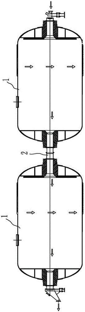
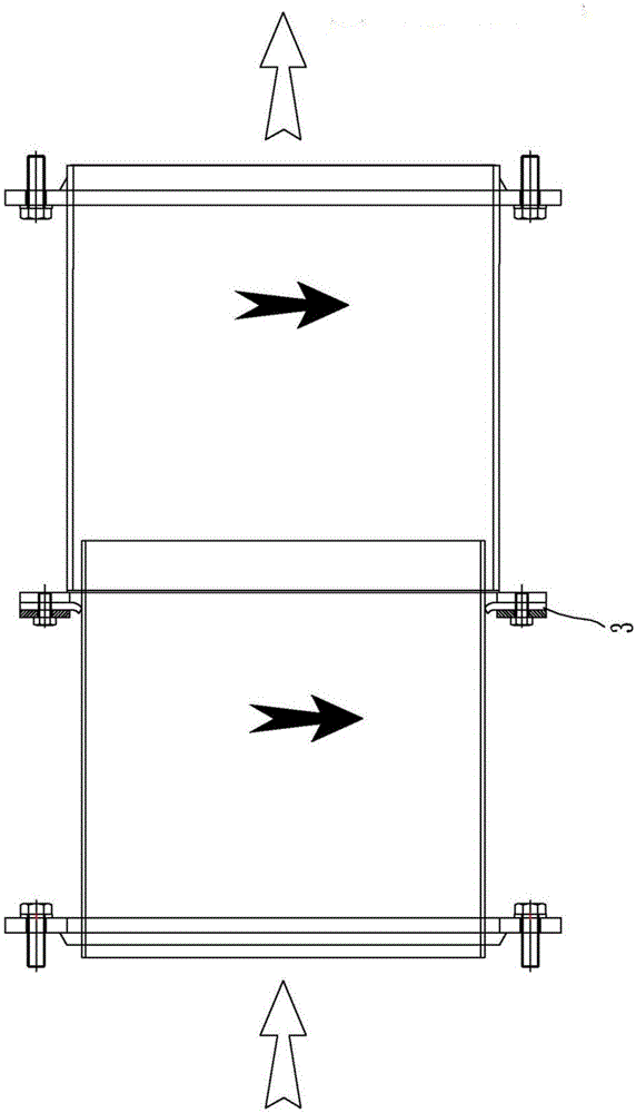
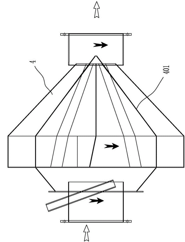
[0014] See attached Figures 3 to 4 As shown, a non-contact pulping device used between continuous ball mills described in this embodiment includes a plurality of ball mill cylinders 1 arranged adjacently, and a plurality of ball mill cylinders 1 arranged between adjacent ball mill cylinders 1 A non-contact pulping device, the non-contact pulping device includes a slurry outlet pipe 5 and a tapered scoop that are fastened respectively at the outlet and inlet of the adjacent pair of ball mill cylinders 1 Slurry cone 4, wherein the above-mentioned slurry outlet pipe 5 is nested in the scooping cone 4, and at the same time, the inner cavity of the scooping cone 4 is also equipped with a plurality of spirals for quickly scooping out the mud. Chute 401.

[0015] At the same time, in order to ensure that the above-mentioned continuous ball mill in this plan can quickly carry out...


PUM


Abstract

The invention provides a non-contact slurry passing device used in a continuous ball mill. The non-contact slurry passing device is simple in structure, stable and reliable in work, long in service life and capable of effectively preventing slurry leaking, and comprises adjacently-arranged ball mill cylinders and further comprises a non-contact slurry passing device body arranged between the adjacent ball mill cylinders. The non-contact slurry passing device body comprises a slurry outlet pipe arranged at a discharging opening and a feeding opening of the adjacent ball mill cylinders in a fastened mode and a conical slurry scooping cone hopper, wherein the slurry outlet pipe is sleeved with the slurry scooping cone hopper in an embedded mode, and meanwhile a plurality of spiral chutes used for rapidly scooping slurry are further distributed in an inner cavity of the slurry scooping cone hopper in the circumferential direction. By means of the scheme, when the non-contact slurry passing device works, the slurry can flow into the slurry scooping cone hopper from the slurry outlet pipe and can be rapidly scooped into the ball mill through the spiral chutes in the slurry scooping cone hopper, the liquid level of the slurry is controlled to be quite low accordingly, then the adjacent ball mill cylinders are not in contact, and it can be guaranteed that the slurry is not leaked in the transmission process.

Description

technical field [0001] The invention relates to the technical field of combined continuous ball mill equipment for silicate industrial wet pulping, in particular to a non-contact slurry passing device used between continuous ball mills. Background technique [0002] See attached figure 1 with 2 As shown, the existing ball mill is more and more recognized and favored by enterprises in the production equipment of building ceramics due to its small footprint, energy saving and many other advantages. At the same time, because the pulping production of the ceramic industry has higher and higher requirements for the flexibility of equipment regulation, the continuous ball mill currently mainly adopts a combined continuous ball mill, that is, the center of several ball mill cylinders 1 is hollowed out and connected with steel pipes 2. In order for the mud to pass through several ball mill barrels 1 smoothly, in addition, in order to improve production efficiency and save energy, ...

Claims


Application Information

Patent Timeline
IPC IPC(8): B02C17/18
CPCB02C17/18
Inventor 胡建国郑渊友陆志勇凌宏伟
Owner 佛山市恒力泰科技有限公司
Why Eureka
Try Eureka