A fast printing fixture for panel surface

A fast, panel technology, used in printing, printing presses, rotary printing presses, etc., can solve the problems of unfavorable enterprises in rapid production, inconvenient adjustment, and large structure.

Active Publication Date: 2017-11-17
SPRING ELECTRONICS WUJIANG
View PDF7 Cites 0 Cited by
  • Summary
  • Abstract
  • Description
  • Claims
  • Application Information

AI Technical Summary

Problems solved by technology

[0002] Existing printing fixtures for panel planes have a large structure and are inconvenient to adjust. When using, the printing screens need to adopt different styles according to different printing surfaces, which is troublesome to replace, and more printing screens need to be customized as spares, which is not conducive to The needs of enterprises for rapid production

Method used


Image

  • A fast printing fixture for panel surface
  • A fast printing fixture for panel surface
  • A fast printing fixture for panel surface

Examples


Embodiment Construction

[0018] The following will clearly and completely describe the technical solutions in the embodiments of the present invention with reference to the accompanying drawings in the embodiments of the present invention. Obviously, the described embodiments are only some, not all, embodiments of the present invention. Based on the embodiments of the present invention, all other embodiments obtained by persons of ordinary skill in the art without creative efforts fall within the protection scope of the present invention.

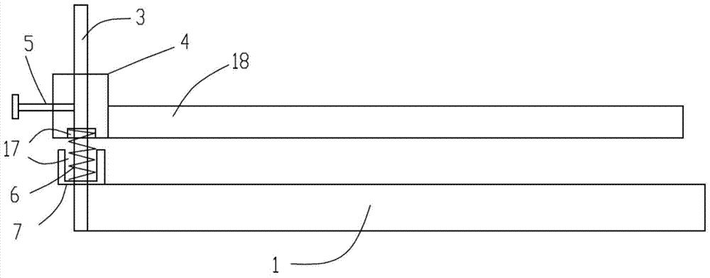
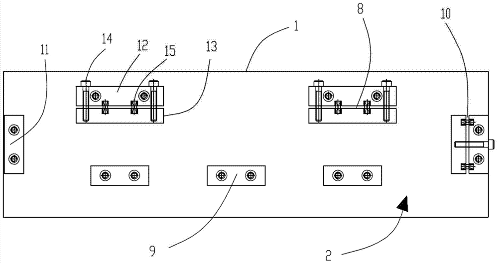
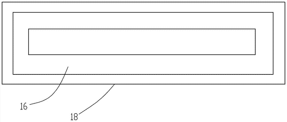
[0019] refer to Figure 1 to Figure 3 As shown, a fast printing fixture for the panel surface includes a bottom plate 1 with a rectangular structure, a clamping mechanism 2 is provided on the surface of the bottom plate, a guide post 3 is vertically provided on the short side of the bottom plate, and a guide sleeve is set on the guide post. 4. One side of the guide sleeve is provided with a knob bolt 5, and the other side is provided with a printing screen 18. The ...


PUM


Abstract

The invention discloses a fast printing jig for panel surface, which comprises a bottom plate with a rectangular structure, the surface of the bottom plate is provided with a clamping mechanism, a short side of the bottom plate is vertically provided with a guide column, and the guide column is covered with A guide sleeve is provided, one side of the guide sleeve is provided with a knob bolt, and the other side is provided with a printing screen, the bottom of the guide sleeve is connected with the positioning sleeve through a spring, the spring sleeve is arranged on the guide column, and the positioning sleeve Screwed with the guide column, the clamping mechanism includes a long-side movable part, a long-side fixed part, a short-side movable part and a short-side fixed part, and the long-side movable part and the short-side movable part are composed of a fixed block, a movable block It is composed of an adjusting screw, the adjusting screw is threadedly connected with the fixed block, and the end of the adjusting screw abuts against the movable block. The invention has simple structure, convenient operation and saves storage space.

Description

technical field [0001] The invention relates to the field of printing, in particular to a fast printing jig for panel surfaces. Background technique [0002] The existing printing fixtures for panel planes have a large structure and are inconvenient to adjust. When using, the printing screens need to adopt different styles according to different printing surfaces, which is troublesome to replace, and more printing screens need to be customized, which is not conducive to The needs of enterprises for rapid production. Contents of the invention [0003] The purpose of the present invention is to overcome the above problems in the prior art, and provide a fast printing fixture for panel surface. The present invention has simple structure, convenient operation, and saves storage space. [0004] In order to achieve the above-mentioned technical purpose and achieve the above-mentioned technical effect, the present invention is realized through the following technical solutions: ...

Claims


Application Information

Patent Timeline
Patent Type & Authority Patents(China)
IPC IPC(8): B41F15/08
Inventor 曾祥兵
Owner SPRING ELECTRONICS WUJIANG
Why Eureka
Try Eureka