

Inhalation sound reduction device
A suction sound reduction and suction pipe technology, applied in the intake muffler, charging system, combustion air/combustion-air treatment, etc., can solve the problem that it is difficult to fully suppress the confluence, and achieve the effect of suppressing abnormal sound
- Summary
- Abstract
- Description
- Claims
- Application Information
AI Technical Summary
Problems solved by technology
Method used
Image

Examples
Embodiment 1
[0035] refer to Figure 1 ~ Figure 3 , the suction noise reduction device according to Embodiment 1 of the present invention will be described.
[0036]
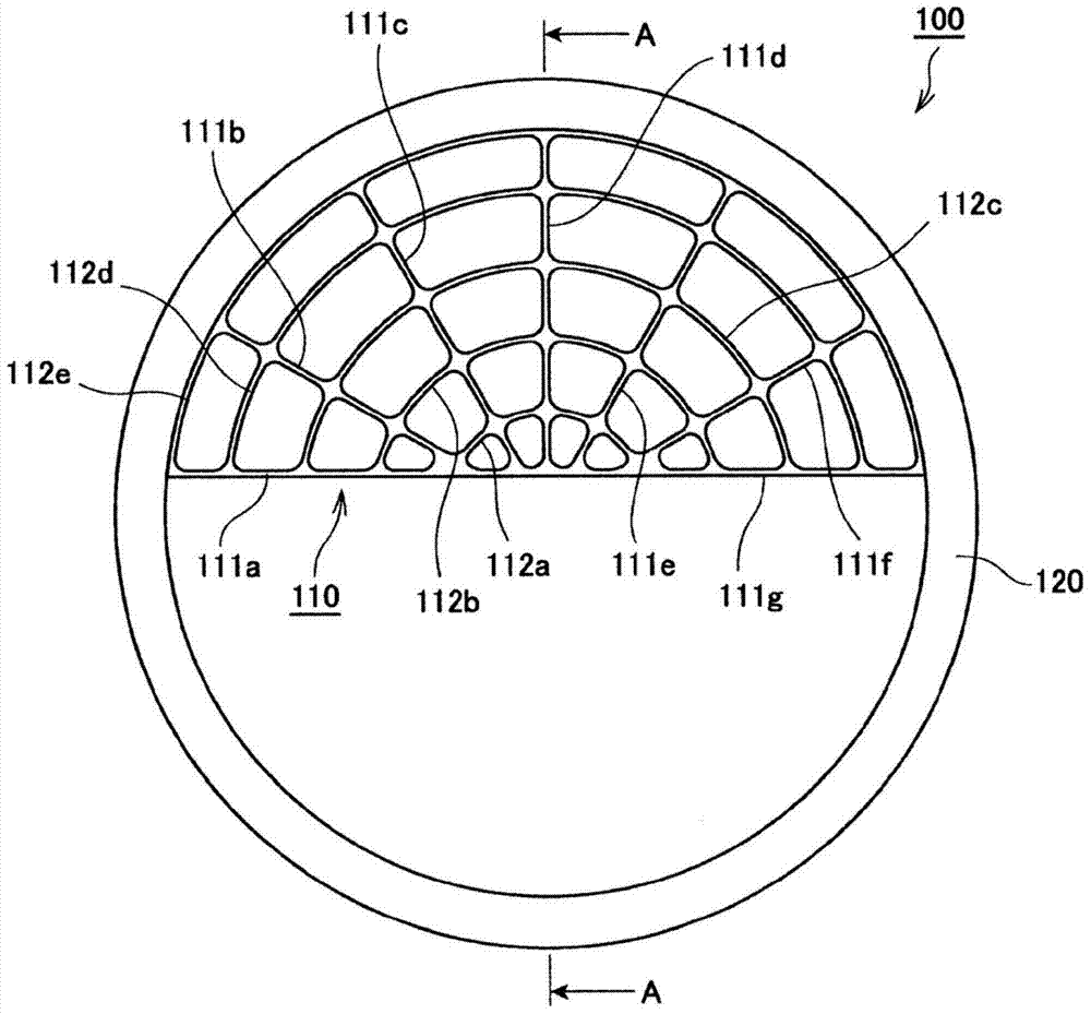
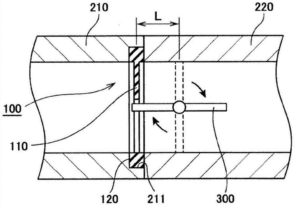
[0037] refer to figure 1 and figure 2 , the structure of the suction noise reduction device of this embodiment will be described. figure 1 It is a plan view of the suction noise reduction device of Example 1 of the present invention. figure 2 It is a schematic cross-sectional view showing the state of use of the air intake sound reducing device according to the first embodiment of the present invention. figure 2 The suction sound reduction device in the figure 1 Cutaway view of AA.
[0038] The intake noise reduction device 100 of the present embodiment is arranged on the downstream side of the throttle valve 300 in the intake pipe. In addition, in the present embodiment, the intake sound reducing device 100 is disposed near the connection portion between the intake manifold 210 and the throttle valve 220 const...
Embodiment 2
[0057] Figure 4 and Figure 5 Embodiment 2 of the present invention is shown. The present embodiment shows a structure in which a cylindrical portion is provided between the rectifying mesh and the gasket portion constituting the suction sound reducing device. The rest of the structure is the same as that of Embodiment 1, so the same reference numerals are attached to the same structural parts and their descriptions are omitted.
[0058] Using the suction pipe and sample S13 used in the above experiment, the distance L between the throttle valve 300 and the suction sound reduction device 100 was changed (refer to figure 2 ), illustrating the experimental results of measuring the sound pressure when the throttle valve 300 starts to open. Figure 4 It is a graph showing the noise sound pressure ratio when the distance L between the throttle valve 300 and the intake sound reducing device 100 is changed.
[0059] In the graph, S21 represents the case where the distance L is ...
Embodiment 3
[0065] Figure 6 Example 3 of the present invention is shown in . Embodiment 1 described above shows the case where the rectifying mesh is provided in the substantially semicircular region inside the gasket portion. This embodiment shows a structure in which the rectifying net is installed over the entire area inside the gasket portion. The other structures and functions are the same as those in Embodiment 1, and the same symbols are assigned to the same structural parts, and therefore description thereof will be omitted.
[0066] The suction noise reduction device 100 of the present embodiment includes a rectifying net 110 and a gasket portion 120 as in the case of the first embodiment described above. In addition, the intake noise reduction device 100 is made of elastic bodies such as various rubber materials or resin elastic bodies, and the rectifying mesh 110 and the gasket portion 120 are integrated. However, it is preferable that the rectifying mesh 110 is made of a r...
PUM
 Abstract
Description
Claims
Application Information