Metal steam discharger lamp

A metal vapor, discharge lamp technology, applied in the direction of gas discharge lamp parts and other directions, can solve the problems of abnormal sound of the outer tube, decreased luminous flux, friction of tongue pieces, etc.

Inactive Publication Date: 2004-05-26
PANASONIC CORP
View PDF1 Cites 0 Cited by
  • Summary
  • Abstract
  • Description
  • Claims
  • Application Information

AI Technical Summary

Problems solved by technology

[0007] Since both ends of the sleeve are sealed with metal plates, the light emitted to the closed part of the outer tube is blocked by the metal plates, so there is a problem of decreased luminous flux
[0008] Moreover, since the outer tube is connected to the tongue piece provided on the metal plate on the side of the closed part of the outer tube, when the light-emitting tube thermally expands or contracts after the light is turned on or off, the metal plate will shrink due to the thermal expansion or contraction of the light-emitting tube. Moving in unison, there will be a problem of abnormal sound caused by the tongue rubbing against the inner surface of the outer tube

Method used


Image

  • Metal steam discharger lamp
  • Metal steam discharger lamp
  • Metal steam discharger lamp

Examples


Embodiment 2

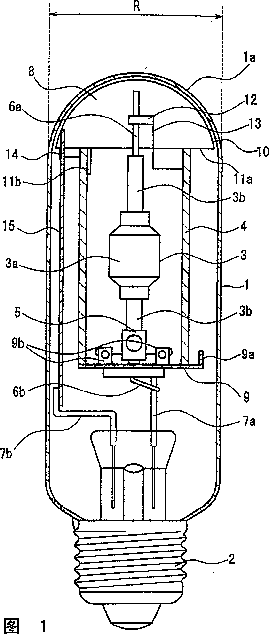
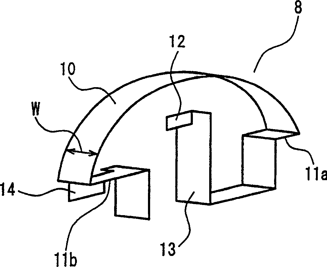
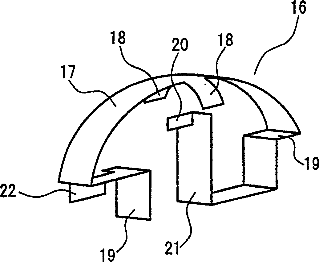
[0076] Next, the metal halide lamp with rated electric power of 150W according to the second embodiment of the present invention, such as image 3 As shown, except that the supporting body 16 is provided with the protruding part 18 that is close to the closed part 1a of the outer tube 1 and protrudes from the pillar part 17, it has the same features as the metal halide lamp with a rated electric power of 150W in the first embodiment of the present invention. structure.

[0077] The protruding portion 18 has a plate shape with a length of 10 mm and a width of 5 mm, is provided at the center of the pillar portion 17 , and protrudes substantially perpendicular to the pillar portion 17 . That is, the pillar portion 17 and the protruding portion 18 form a cross shape. The pillar portion 17 and the protruding portion 18 are formed of one plate.

[0078] image 3 Among them, 19 denotes a sleeve holding portion, 20 denotes a power supply body connection portion, 21 denotes an elast...

Embodiment 3

[0081] Next, the metal halide lamp with a rated electric power of 150W according to the third embodiment of the present invention is as follows: Figure 4 As shown, in the supporting body 23, except that the elastic body part 26 composed of a stretchable coil spring is interposed between the sleeve holding part 24a and the power supply body connecting part 25, the rest has the same characteristics as the first embodiment of the present invention. The same structure as a metal halide lamp with a rated electric power of 150W.

[0082] The elastic body portion 26 is composed of molybdenum and has a length of 5 mm and a diameter of 5 mm.

[0083] Figure 4 Among them, 24 denotes another sleeve holding portion, 27 denotes a support portion, and 28 denotes an electric power supply line connection portion.

[0084] According to the structure of the third embodiment of the present invention as above, it is possible to firmly support the sleeve 4 while also suppressing the occurrence...

Embodiment 4

[0087] The halogen lamp with a rated electric power of 150W in the fourth embodiment of the present invention is as Figure 5 As shown, in the support body 29, except that the sleeve holders 31a, 31b are arranged with the outer tube 1 shown in FIG. 1 ( Figure 5 Not shown) of the blocking portion 1a ( Figure 5 not shown) side bushing 4 ( Figure 5 (not shown) except for the recessed grooves 30a, 30b with a width of 1.3mm and a depth of 2mm, which are fitted at the ends of the lamp, the remaining structure is the same as that of the halogen lamp rated at 150W in the first embodiment of the present invention.

[0088] Figure 5 Among them, 32 denotes a support portion, 33 denotes a power supply body connection portion, 34 denotes an elastic body portion, and 35 denotes a power supply line connection portion.

[0089] According to the structure of the fourth embodiment of the present invention as described above, the bushing 4 can be firmly supported, and the occurrence of ab...


PUM


Abstract

A metal vapor discharge lamp including an outer tube having a closed portion at a first end and a base at a second end; a discharge tube inside of which an electrode is provided, located in the outer tube; and a sleeve enveloping the discharge tube and located in the outer tube, wherein the sleeve includes an open portion on the closed portion side of the outer tube; the closed portion side of the outer tube is provided with a support for supporting an end of the closed portion side of the sleeve; the support comprises a column portion having a narrow plate shape or a narrow stick shape separated from the open portion of the closed portion side of the sleeve, and a sleeve holding portion provided at an end of the column portion and is in contact with the sleeve; and the support is connected to a feeding body connected to the electrode and led from the discharge tube toward the side of the closed portion, and the support also is connected to an electric power supply wire extending toward the side of the base. Thereby, it is possible to provide a high efficiency and long lifetime metal vapor discharge lamp capable of suppressing abnormal noises after the lamp is turned on or off with the sleeve supported firmly.

Description

technical field [0001] The invention relates to metal vapor discharge lamps. Background technique [0002] Existing metal vapor discharge lamps, for example, metal halide lamps, in order to prevent damage to the outer tube caused by the rupture of the luminous tube at the end of life, it is proposed to surround the luminous tube with a glass cylindrical sleeve (hereinafter referred to as the sleeve) and A device in which the two ends of the casing are sealed with metal plates (JP-A-2-230655). [0003] The metal plate is provided with tongues respectively connected with the outer tube and the sleeve, so that the tongues are in contact with the inner surface of the outer tube, thereby keeping the sleeve at a specified position in the outer tube. [0004] Recently, such conventional metal halide lamps use light-transmitting ceramic arc tubes that are excellent in heat resistance and halogen resistance. The conventional metal halide lamp using the ligh...

Claims


Application Information

Patent Timeline
Patent Type & Authority Patents(China)
IPC IPC(8): H01J61/34H01J61/50
CPCH01J61/34
Inventor 柿坂俊介西浦义晴
Owner PANASONIC CORP
Why Eureka
Try Eureka