
Internal structure of FCC stripper and its arrangement method

A technology for catalytic cracking and internal components, applied in catalytic cracking, chemical instruments and methods, cracking, etc., can solve problems such as oil and gas coking, and achieve the effects of preventing oil and gas coking, large reserves, and increased processing capacity

Active Publication Date: 2006-04-26
CHINA PETROLEUM & CHEM CORP
View PDF2 Cites 15 Cited by
  • Summary
  • Abstract
  • Description
  • Claims
  • Application Information

AI Technical Summary

Problems solved by technology

However, this stripping packing structure also has a local fluidized dead zone, which is prone to oil and gas coking when it is used for the stripping of the spent agent.

Method used


Image

  • Internal structure of FCC stripper and its arrangement method
  • Internal structure of FCC stripper and its arrangement method
  • Internal structure of FCC stripper and its arrangement method

Examples


Embodiment

[0040] This embodiment illustrates: the implementation effect of the internal member of the present invention.

[0041] Figure 7 It is a schematic structural diagram of the cold-state experimental device adopted in this embodiment. The device is a circulating fluidized device, as shown in the figure, the catalyst is lifted to the settler 32 in the riser 37, and after the two-stage separation of the swirl head 38 and the cyclone separator 31, it enters the stripping section 33 and is stripped. After completion, it enters the storage bin 34, quantitatively feeds the pre-lifter 36 through the screw feeder 35, and then enters the riser 37 for the next round of circulation. The diameter of the stripping section used in the experiment is 200mm, the total height is 1.5m, the diameter of the riser is 80mm, and the height is 4.5m. In the experiment, carbon dioxide gas was used as the fluidization gas in the stripping section 33, and the air entrained by the catalyst particles flowin...


PUM


Abstract

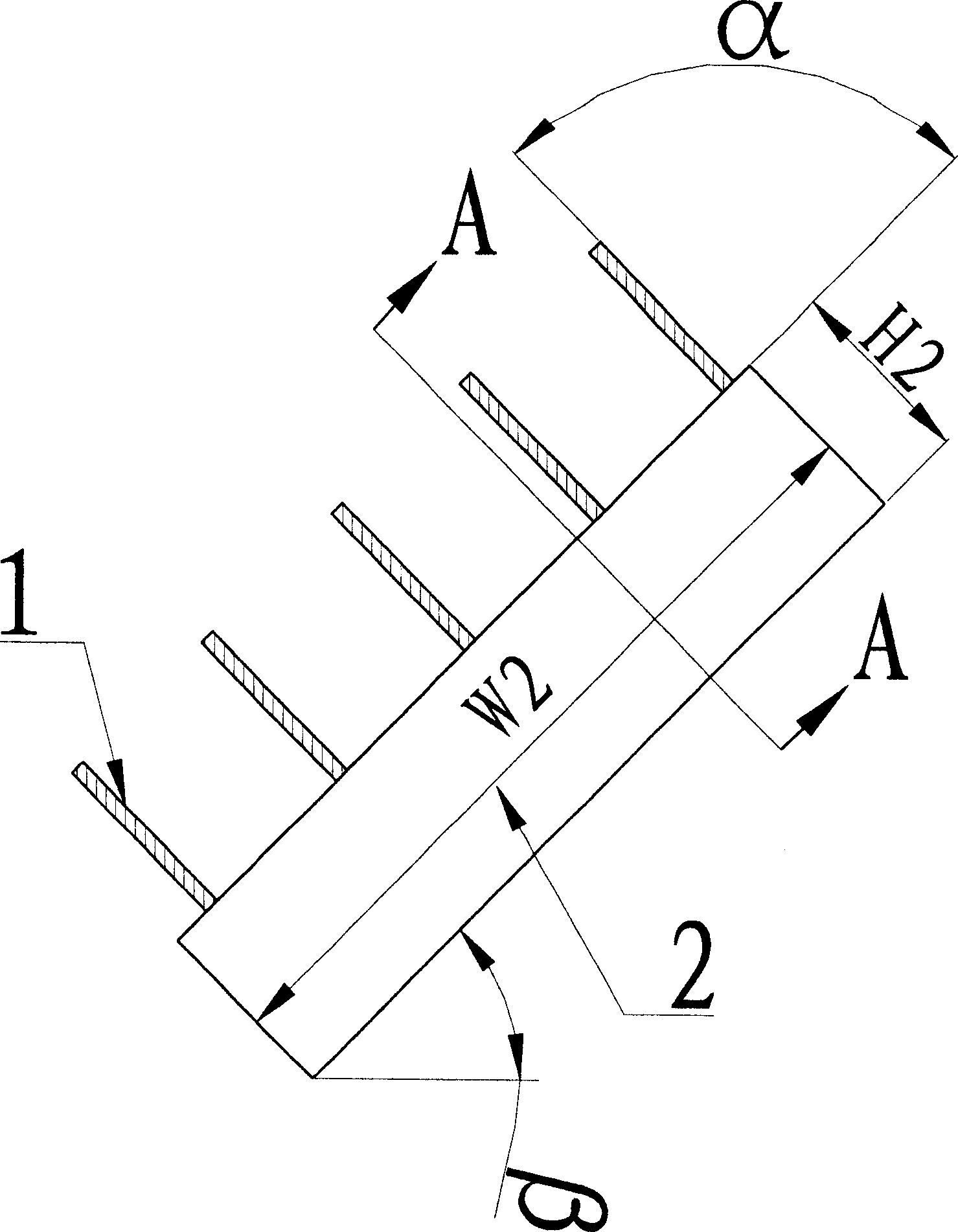
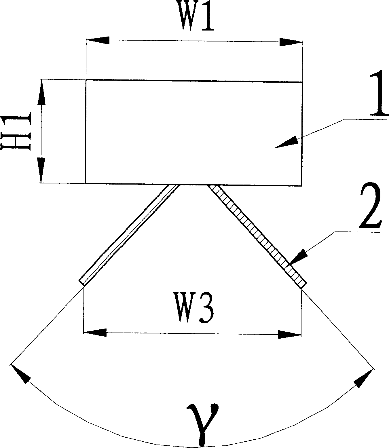
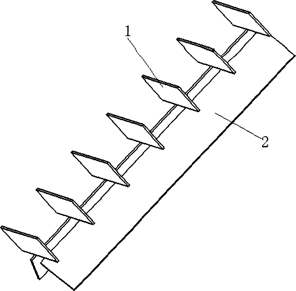
The present invention is inside members of catalytically cracking stripper plant and their configuration. Each of the inside members include two or more auxiliary guide blades and two main guide blades connected to the auxiliary guide blades in splay configuration. The inside members may be either one-by-one filled into the catalytically cracking stripper plant or made into stuffing block filled into the catalytically cracking stripper plant. The inside members and corresponding configuration of the present invention can raise stripping efficiency obviously.

Description

technical field [0001] The invention relates to a stripper internal component used in a catalytic cracking process and a setting method thereof. Background technique [0002] Fluid Catalytic Cracking (FCC) is an important secondary processing process in the petroleum refining industry, which uses heavy feedstock oil to produce light oil products such as gasoline, diesel, and liquefied petroleum gas. The main steps are as follows, the hydrocarbon raw material is contacted with the hot regenerated catalyst in the riser, and the catalytic cracking reaction is carried out at 450 ° C ~ 550 ° C; after the reaction, the mixture of oil gas and the catalyst to be regenerated enters the settler, and is cyclone separated in the settler The unproductive catalyst is separated by the device and enters the stripper, while the oil and gas enters the subsequent product separation system. The raw catalyst is in countercurrent contact with water vapor in the stripper, and after removing the e...

Claims


Application Information

Patent Timeline
IPC IPC(8): C10G11/18B01J8/34
Inventor 张永民龙军侯栓弟张占柱张久顺鲁维民许克家
Owner CHINA PETROLEUM & CHEM CORP
Learn More