Pump assembly and method for evacuating a vapor-filled chamber

A component, chamber technology that can be used in parts of pumping devices for elastic fluids, pump elements, rotary piston/oscillating piston pump components, etc., and can solve problems such as large amounts of water, low condensing temperatures, etc.

Active Publication Date: 2015-11-04
STERLING IND CONSULT GMBH
View PDF7 Cites 10 Cited by
  • Summary
  • Abstract
  • Description
  • Claims
  • Application Information

AI Technical Summary

Problems solved by technology

The disadvantage of this type of heat exchanger is that a large am

Method used


Image

  • Pump assembly and method for evacuating a vapor-filled chamber
  • Pump assembly and method for evacuating a vapor-filled chamber

Examples


Embodiment Construction

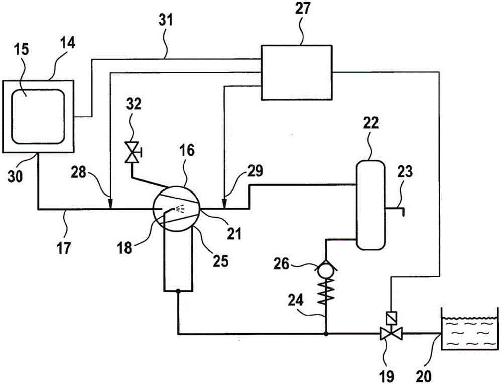
[0032] figure 1 Among other things, the assembly according to the invention comprises an autoclave 14 as used especially in hospitals to sterilize clothing, towels, bedding and also instruments. The autoclave 14 comprises a chamber 15 which can be closed such that the chamber 15 is sealed. Thus, the chamber 15 can be placed under overpressure or vacuum.

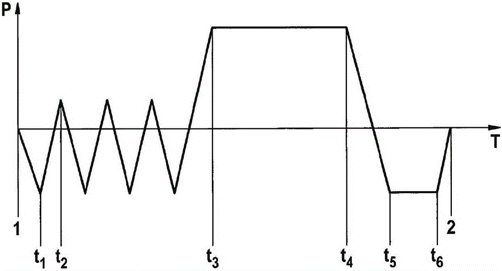
[0033] Taking towels as an example, with the help of figure 2Explain the sanitization cycle. exist figure 2 In the graph of , the pressure P in the chamber 15 is applied over time T. In the initial state, the chamber 15 is at an atmospheric pressure of about 1 bar. flap (not in figure 1 shown in ) is opened, and a towel is placed in chamber 15.

[0034] The chamber is evacuated to a pressure of approximately between 100 mbar and 120 mbar until time t1 . This draws air containing bacteria out of the chamber 15 . A steam flow is then generated, by means of which the chamber 15 is completely filled with steam between ...


PUM


Abstract

The invention relates to an assembly comprising a vacuum pump (16) and a chamber (15), wherein a suction tract (17) extends between the chamber (15) and the vacuum pump (16). The vacuum pump (16) is a liquid ring machine. According to the invention, a liquid outlet (18) is arranged in the suction tract (17) in order to add liquid to gas sucked in from the chamber (15). The invention further relates to a method for evacuating a chamber (15) filled with vapor. According to the invention, the vapor is condensed by introducing additional liquid into the suction tract, thus by co-condensation. By supplying liquid selectively only when liquid is required for the condensation of the vapor, water is saved.

Description

technical field [0001] The invention relates to an assembly made of a vacuum pump and a chamber, wherein an inlet channel extends between the chamber and the vacuum pump. The vacuum pump is a liquid ring machine. The invention also relates to a method for evacuating a chamber filled with steam. Background technique [0002] For example, autoclaves as used in hospitals for sterilizing eg towels, bedding or instruments are among the applications in which a steam-filled chamber is evacuated. Hot steam is introduced into the chamber for sterilization purposes. Once sterilization has been completed, steam is drawn out of the chamber of the autoclave so that the sterilized items can be removed. Because of this, it is not possible to simply export the steam into the environment. So, in the process, the steam is condensed so that only condensate remains. [0003] A vacuum pump connected to the autoclave chamber by means of an air inlet channel was used to evacuate the gases. A...

Claims


Application Information

Patent Timeline
IPC IPC(8): F04B43/06F04B37/14
CPCF04C29/042F04C19/004F04C2210/1077F04C2220/10F04C23/00F04C25/02F04C19/001F04C28/10
Inventor 海纳·科斯特马提亚·塔姆丹尼尔·舒策
Owner STERLING IND CONSULT GMBH
Why Eureka
Try Eureka