Hollow brick structure for installing in-wall heating pipe

A hollow brick and heating technology, which is applied to building components, building structures, buildings, etc., can solve the problems of hollow brick structures without practical heating and heat pipes, low shear and tensile strength of walls, and inability to be used as load-bearing walls.

Active Publication Date: 2015-11-11
湖南舒吕建材科技有限公司
6 Cites 0 Cited by

AI-Extracted Technical Summary

Problems solved by technology

[0003] The hollow bricks are only bonded by mortar, resulting in low shear and tensile strength of the wall, which cannot be used as a load-bearing wall
Most of the current heating pipes are installed on the floor, but the floor...

Method used

[0018] The upper surface of the mounting plate 4 is provided with a heater heat pipe installation groove, and the installation groove is arc-shaped and matches the outer surface of the heater heat pipe, which is conducive to a better electric heater heat pipe. Each heating heat pipe is installed in the corresponding installation groove, so that the heating heat pipe is close to the outer surface of the main body 1, and the heat transfer to the outside of the wall is faster, and a static air layer is formed inside to prevent the temperature from spreading to both sides, so it has better heat insulation effect, and increase the remaining space in the heating space 3, better reduce heat transfer,
[0019] The left and right sy...

Abstract

The invention discloses a hollow brick structure for installing an in-wall heating pipe. The hollow brick structure for installing the in-wall heating pipe comprises a main body, wherein a heating space for installing the heating pipe is arranged in the main body, an installation plate for installing the heating pipe is arranged in the heating space, and the installation plate is horizontally placed in the heating space; the left and right ends of the main body are provided with through holes; heat insulation plates are further arranged on the inner walls of the heating space, and the heat insulation plates are in close contact with the inner left and right walls of the heating space; plate ribs are arranged in the through holes. The hollow brick structure for installing the in-wall heating pipe has the beneficial effects that since the heating pipe is installed in the heating space and is close to the surface of the main body, heat can be more quickly transferred towards the outside of the wall; since the left and right ends of the main body are provided with the through holes, the heat is prevented from being diffused towards two sides; since the plate ribs are arranged in the through holes, the shear and tensile strength of the hollow brick is improved.

Application Domain

Building components

Technology Topic

Close contactChemical engineering +1

Image

  • Hollow brick structure for installing in-wall heating pipe

Examples

  • Experimental program(1)

Example Embodiment

[0016] The present invention will be further elaborated below in conjunction with the accompanying drawings and specific embodiments.
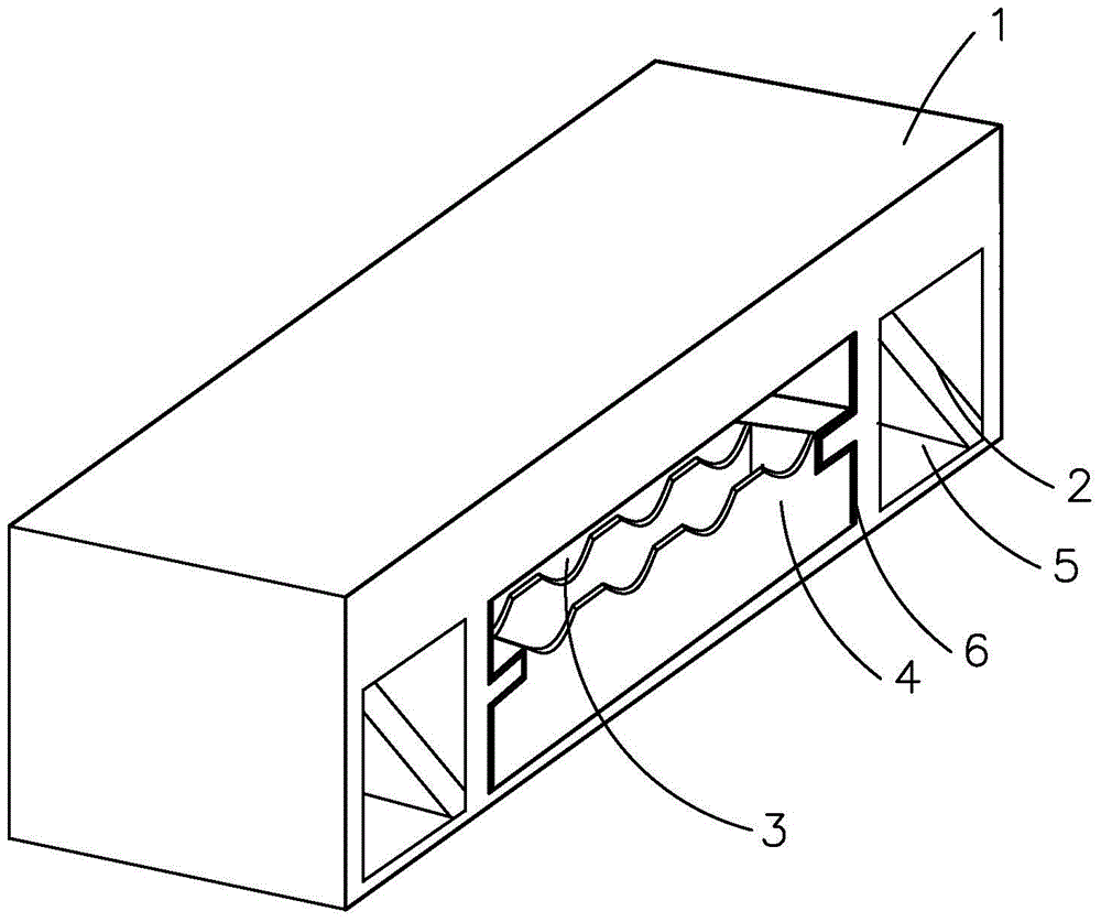
[0017] As shown in Figure 1, a hollow brick structure for installing heating in the wall includes a main body 1, and a heating space 3 for installing heating heat pipes is provided in the main body 1. A mounting plate 4 for installing heating heat pipes is also provided in the main body 1, The preferred mounting plate 4 is thermal insulation asbestos with a thickness of 10 mm, and the mounting plate 4 is placed horizontally in the heating space 3;
[0018] The upper end surface of the mounting plate 4 is provided with a heater heat pipe installation groove, and the installation groove is arc-shaped to match the outer surface of the heater heat pipe, which is beneficial to better install the electric heater heat pipe. Each heating heat pipe is installed in the corresponding installation groove, so that the heating heat pipe is close to the outer surface of the main body 1, and the heat transfer to the outside of the wall is faster, and a static air layer is formed inside to prevent the temperature from spreading to both sides, so it has better heat insulation effect, and increase the remaining space in the heating space 3, better reduce heat transfer,
[0019] Two symmetrical positions on the left and right of the main body 1 are provided with through holes 5, the through holes 5 run through the entire main body 1, and the inside of the through holes 5 are provided with ribs 2 to improve the low shear tensile strength of the hollow brick. The inner wall of the heating space 3 is also provided with a thermal insulation board 6, the preferred thickness of the thermal insulation board 6 is 10mm, and the thermal insulation board 6 is closely attached to the left and right inner walls of the heating space 3; while reducing the weight of the heat-insulating floor heating floor. It reduces the heat transfer between the temperature and the two sides, and the through hole 5 is square to facilitate processing.
[0020] Those skilled in the art will appreciate that the embodiments described here are to help readers understand the principles of the present invention, and it should be understood that the protection scope of the present invention is not limited to such specific statements and embodiments. Those skilled in the art can make various other specific modifications and combinations based on the technical revelations disclosed in the present invention without departing from the essence of the present invention, and these modifications and combinations are still within the protection scope of the present invention.

PUM

PropertyMeasurementUnit
Thickness10.0mm

Description & Claims & Application Information

We can also present the details of the Description, Claims and Application information to help users get a comprehensive understanding of the technical details of the patent, such as background art, summary of invention, brief description of drawings, description of embodiments, and other original content. On the other hand, users can also determine the specific scope of protection of the technology through the list of claims; as well as understand the changes in the life cycle of the technology with the presentation of the patent timeline. Login to view more.
Why Eureka
Try Eureka