A kind of split wire clamp hardware

A technology of wire clip fittings and split wires, which is applied in the direction of electrical components, circuits, connections, etc., can solve problems such as unstable conduction flow performance, achieve unstable conduction flow performance, improve flow performance, and increase conductivity The effect of contact area

Active Publication Date: 2018-04-03
PINGGAO GRP +1
View PDF4 Cites 3 Cited by
  • Summary
  • Abstract
  • Description
  • Claims
  • Application Information

AI Technical Summary

Problems solved by technology

[0003] The purpose of the present invention is to provide a split wire clamp fitting, which aims to solve the problem of unstable conduction and flow performance between the terminal board and the fitting in the prior art

Method used


Image

  • A kind of split wire clamp hardware
  • A kind of split wire clamp hardware
  • A kind of split wire clamp hardware

Examples


Embodiment Construction

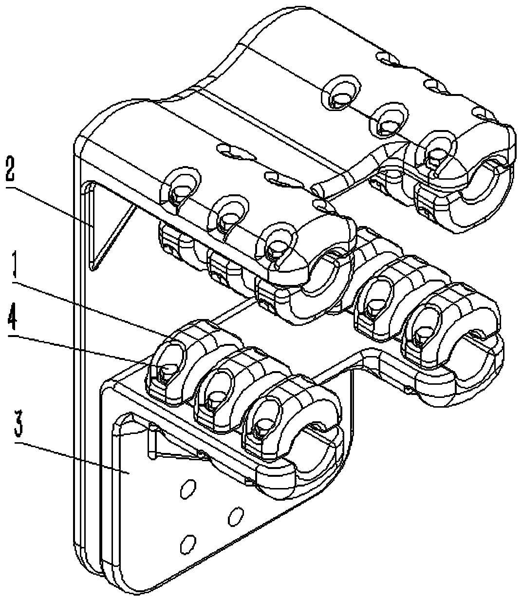
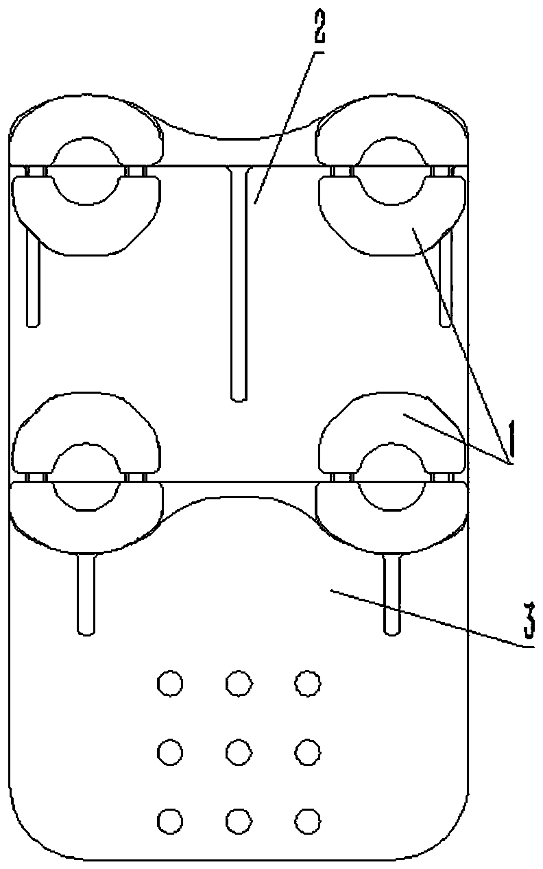
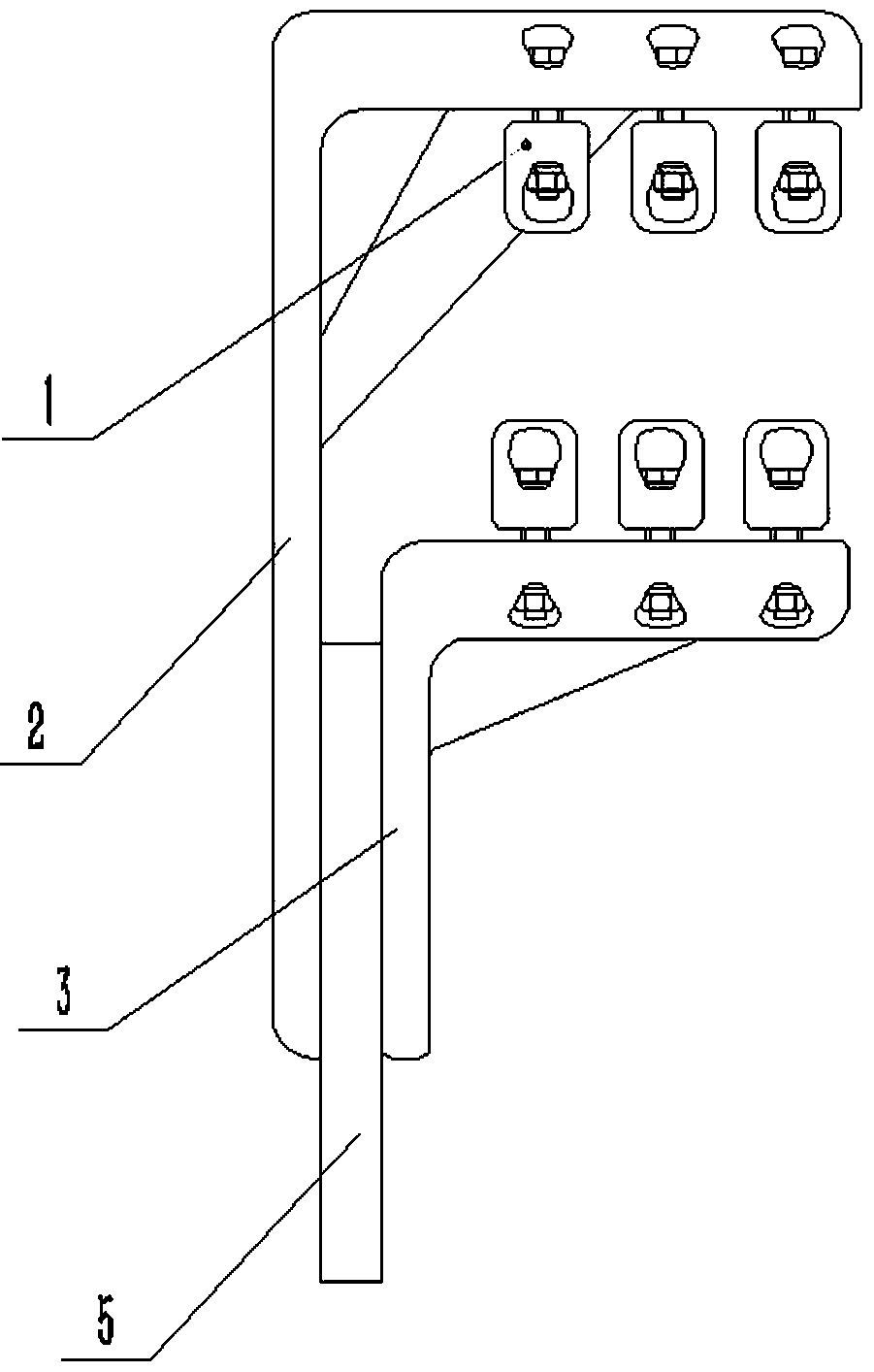
[0025] The embodiment of middle wire clip gold tool of the present invention: as Figure 1 to Figure 12 As shown, the wire clamp fitting is a split wire clamp fitting used in the T-connection conversion between the four-split wire and the terminal board 5. It is mainly composed of a wire clamp cover plate 1, an upper splint plate 2 and a lower The cover plate is composed of the clamp cover plate 1, the upper clamp plate 2 and the lower cover plate are all made of ZL101A cast aluminum-silicon alloy, which reduces the weight and increases the strength, and has the properties of high temperature resistance and corrosion resistance.

[0026] The upper splint 2 is an L-shaped plate formed by integrally connecting the upper plate 21 and the front vertical plate 22 . The upper plate 21 is bent backward at the top of the front vertical plate 22, and the upper splint 2 includes upper fixed clip parts arranged on the left and right sides. The top surface of 21, the outer convex surface...


PUM


Abstract

The invention discloses a split wire clamp hardware. The terminal interface of the wire clamp hardware is provided with two terminal splints for relatively clamping the terminal board. The conductive contact surfaces on both sides of the board, and the two terminal splints are correspondingly provided with fastening holes extending in opposite directions. In this way, when conducting conductive connection with the terminal board, the terminal board is clamped between the two terminal splints, and the conductive contact surfaces on the opposite side plates of the two terminal splints are in contact with the wires on both sides of the terminal board to realize current conduction In this way, when the bolt connection between the hardware and the terminal board is loose, one of the two terminal splints is always in close contact with the terminal board. The conductive contact between the terminal splint and the terminal board can increase the conductive contact area and further improve the flow performance.

Description

technical field [0001] The invention relates to a split wire clamp hardware. Background technique [0002] At present, with the increasing domestic power demand, the capacity and carrying capacity of conventional converter stations cannot meet the actual needs gradually, and the clamp fittings used in conventional converter stations cannot meet the requirements of new UHVDC converter stations. For example, the Chinese patent document CN 103701078 A (published on April 2, 2014) discloses "a wire connection fitting for UHV converter stations", including a flat port for connecting a flat terminal board, The first port for connecting the first wire and the second port for connecting the second wire, wherein one side of the terminal board is attached to the flat port and fastened by bolt connection; the first port is The six-claw type first fixed gripper fixed on the flat port, each claw of the first fixed gripper is respectively connected to one of the six split wires; the seco...

Claims


Application Information

Patent Timeline
Patent Type & Authority Patents(China)
IPC IPC(8): H01R11/14
Inventor 宋铁创常林晶徐健涛李俊辉杨国华尹天朔康博
Owner PINGGAO GRP
Why Eureka
Try Eureka