Vehicle with front area

A technology for automobiles and areas, applied in the direction of body, body stability, vehicle components, etc., can solve problems such as insufficient brake cooling

Active Publication Date: 2012-07-25
DR ING H C F PORSCHE AG
View PDF1 Cites 2 Cited by
  • Summary
  • Abstract
  • Description
  • Claims
  • Application Information

AI Technical Summary

Problems solved by technology

[0004] The cooling air inlets known from the prior art only have an insufficient cooling effect on the brakes at high speeds, especially on racing cars intended for high speeds

Method used


Image

  • Vehicle with front area
  • Vehicle with front area
  • Vehicle with front area

Examples


Embodiment Construction

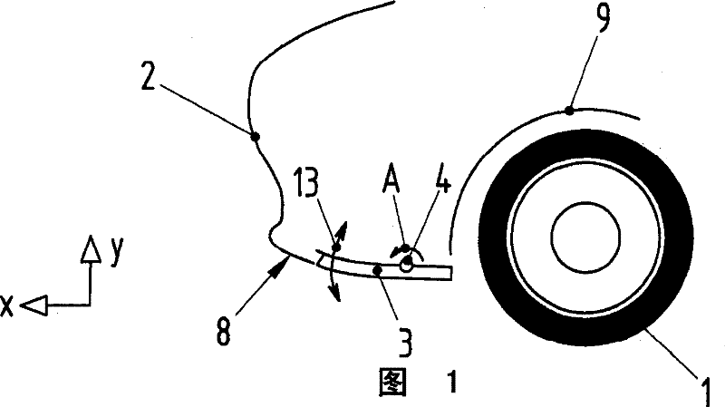
[0027] figure 1 A schematic view of the front region of a motor vehicle with a front component 2 is shown. The underside of the front area faces the roadway during normal traction of the car. During towing, an underbody airflow forms between the underside of the vehicle and the roadway. In addition, in figure 1 A wheel 1 of a front axle of a motor vehicle is shown schematically in , wherein the wheel 1 is arranged in a wheel housing 9 which is only shown schematically. Wheel 1 is equipped with at least one wheel brake, not shown in detail. On the underside of the front area, a channel 3 is provided in front of the wheel 1 . The channel 3 is in figure 1 In the first position shown in , it is substantially aligned with the underside 8 of the front area of ​​the motor vehicle.

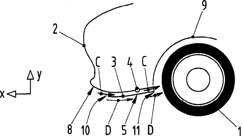
[0028] Channel 3 is rotatably supported about a rotational axis 4 and can be figure 1 The schematically shown first position translates to figure 2 The second position shown schematically in . A...


PUM


Abstract

The invention relates to a vehicle having a front area; the bottom side of the front area facing to the roadway is provided with a channel (3) for supplying cooling air to wheel brakes (7) of the vehicle. The channels (3) are provided with a closed profile and configured to rotate between the first position and the second position along a rotation shaft (4); wherein, the channels (3) in the firstposition align with a floor space (8) within a front region of the vehicle. The channels (3) in the second position supply the cooling air to the wheel brakes (7). According to the invention, the effective cooling air satisfying the demand is supplied to the wheel brakes of the vehicle.

Description

technical field [0001] The invention relates to a motor vehicle having a front region in which ducts are provided on the underside facing the roadway for introducing cooling air to the wheel brakes of the motor vehicle. Background technique [0002] The motor vehicle mentioned at the outset is known, for example, from DE 35 42 376 A1. The motor vehicle described here has a front part, which is connected to air ducts for cooling the brakes, wherein the air ducts are integrally formed with the front part, and wherein the air ducts At least in one region of its longitudinal extent there is a groove open for the driveway. The air ducts described in DE 35 42 376 A1 increase the air resistance of the vehicle and, moreover, have a negative effect through increased fuel consumption and increased noise. [0003] In order to reduce the air resistance when the brakes do not need to be cooled, it is proposed in DE 42 29 945 B4 that rotatable covers can be provided in the channels for ...

Claims


Application Information

Patent Timeline
Patent Type & Authority Patents(China)
IPC IPC(8): B60T5/00
CPCB60T5/00B62D35/00B62D37/02
Inventor T・沃尔夫
Owner DR ING H C F PORSCHE AG
Why Eureka
Try Eureka