Vibration motor electronic equipment

A vibration motor and driving force technology, applied in the mechanical field, can solve the problems of single vibration feedback and inability to achieve multi-directional vibration feedback.

Active Publication Date: 2015-11-11
GOERTEK INC
View PDF5 Cites 32 Cited by
  • Summary
  • Abstract
  • Description
  • Claims
  • Application Information

AI Technical Summary

Problems solved by technology

[0005] The present invention provides a vibration motor and electronic equipment to solve the problem...

Method used


Image

  • Vibration motor electronic equipment
  • Vibration motor electronic equipment
  • Vibration motor electronic equipment

Examples


Embodiment 1

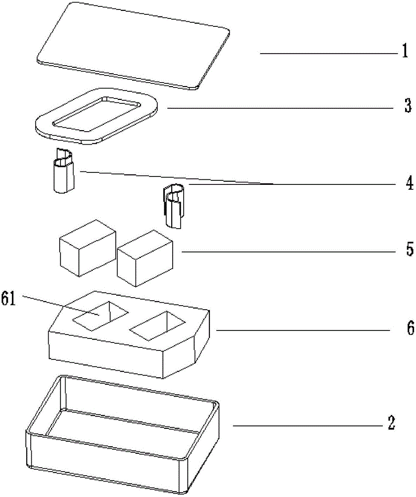
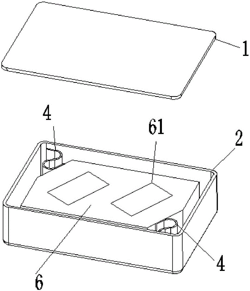
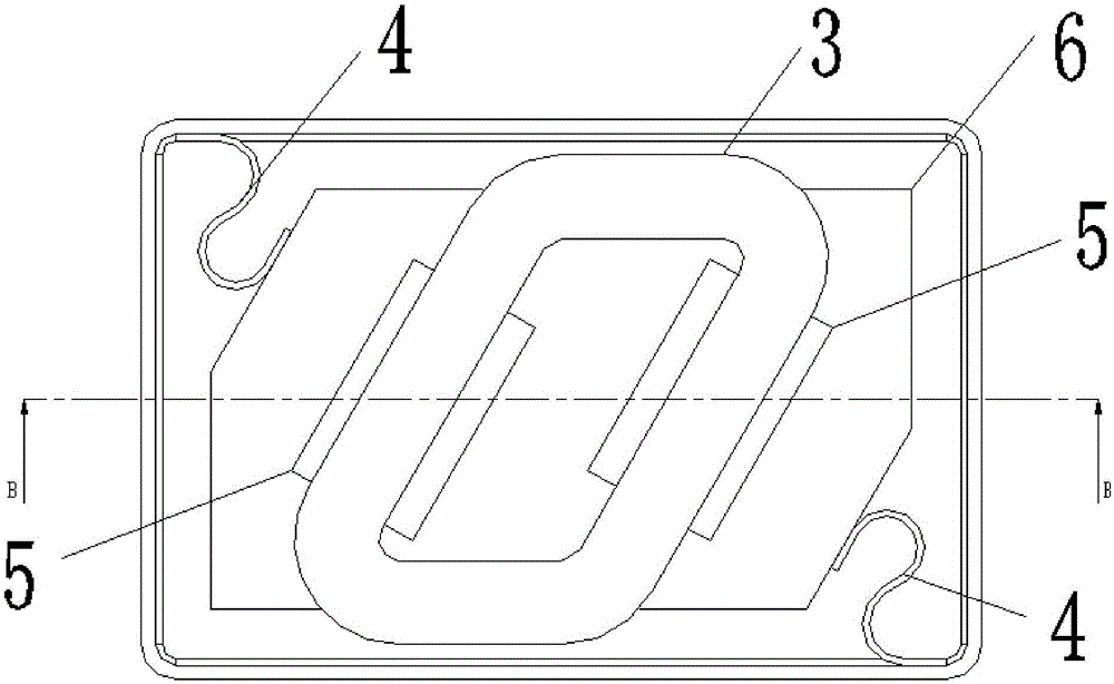
[0032] figure 1 An exploded view of the vibration motor provided in Embodiment 1 of the present invention, figure 2 for figure 1 The schematic diagram of the assembled body of the vibration motor in , image 3 is the top view of 2, Figure 4 for image 3 Sectional view at BB.

[0033] like Figure 1 to Figure 4 As shown collectively, the vibration motor of this embodiment includes a casing composed of an upper casing 1 and a lower casing 2 , and the cavity surrounded by the casing accommodates a coil 3 , shrapnel 4 , magnet 5 and mass 6 .

[0034] The mass block 6 has an accommodating groove 61 adapted to the outline of the magnet 5, and the magnet 5 is accommodated in the accommodating groove 61 for providing a magnetic field for the vibration motor;

[0035] The coil 3 is fixed on the upper shell 1 and is connected to an external power source for inductively generating a driving force with the magnet 5 when energized;

[0036] A shrapnel 4 is arranged at a pair of co...

Embodiment 2

[0047] like Image 6 As shown, the vibration motor of this embodiment also includes a pot frame 7, which is fixed on the upper shell 1 and has a housing structure 71 adapted to the outline of the coil 3, and the coil 3 is embedded in the housing structure 71 of the pot frame 7 ; Wherein, the frame 7 is a soft magnetic metal magnetic material.

[0048] In this embodiment, the coil is embedded in a frame made of magnetically conductive material, and the frame is used to gather and constrain the self-diverging magnetic field lines in the magnetically conductive material, and transmit it to the power system part of the vibration motor to achieve The purpose of improving the utilization rate of magnetic induction lines and improving the vibration performance of the motor. In practical applications, the vibration motor of the present invention may also include structures such as washer boards and edge washer, so as to further improve the utilization rate of magnetic induction lines...

Embodiment 3

[0050] This embodiment provides an electronic device, including the first embodiment and / or the vibration motor provided by the embodiment, and utilizes the characteristic of the motor's diagonal vibration to realize multi-directional tactile and vibration feedback experiences of the device, thereby improving user experience.

[0051] The electronic equipment in this embodiment can better adapt to the development requirements for precision miniaturization, fast pace, high quality and low cost by using the vibration motor.

[0052]In summary, the present invention provides a vibrating motor and electronic equipment. The mass block of the vibrating motor is connected to the diagonal of the housing by a shrapnel, so that the magnet embedded in the mass block can realize diagonal vibration during electromagnetic induction. . Diagonal vibrating motors can not only achieve multi-directional vibration effects of X-direction vibration and Y-direction vibration, resulting in a better u...


PUM


Abstract

Disclosed in the invention is a vibration motor comprising a housing formed by an upper shell 1 and a lower shell 2. A coil 3, spring plates, magnets, and a mass block are accommodated into a cavity encircled by the housing. The mass block 6 contains accommodation grooves 61 with the shapes matching the external profiles of the magnets 5; and the magnets 5 are accommodated into the accommodation grooves 61 and are used for providing magnetic fields for the vibration motor. The coil 3 that is fixed on the upper shell 1 and is connected with an external power supply is used for making induction with the magnets 5 during electrification to generate a driving force. The spring plates 4 are respectively arranged at diagonal positions of the lower shell 2. The mass block 6 that is connected to the lower shell 2 by the spring plates and is suspended inside the housing makes vibration horizontally along the diagonal direction of the housing under the effect of the driving force. According to the invention, the diagonal vibration of the motor can be realized and thus a multi-azimuth vibration effect with vibration at the X direction and the Y direction can be realized, so that the good user experience can be provided. Moreover, on the basis of the principle that the diagonal line is the longest, displacement needed by vibration can be met and thus space is saved.

Description

technical field [0001] The invention relates to the mechanical field, in particular to a vibration motor and electronic equipment. Background technique [0002] Currently, the vibrators or motors of existing electronic products on the market generally vibrate in the Z direction or the X direction, and the vibration feedback is relatively simple, which makes it impossible for consumers to achieve a multi-range tactile and vibration feedback experience. [0003] The pure X-direction or other vibration requires a lot of product space, which is an obstacle to the increasingly miniaturized development of products. [0004] In view of the fact that products are becoming more and more sophisticated, miniaturized, fast-paced, high-quality, and low-cost, and the body is getting thinner and thinner, a new vibration motor is urgently needed to meet market demand. Contents of the invention [0005] The invention provides a vibrating motor and electronic equipment to solve the problem...

Claims


Application Information

Patent Timeline
IPC IPC(8): H02K33/02
Inventor 祖峰磊李勇
Owner GOERTEK INC
Why Eureka
Try Eureka