
Radio communication distance testing apparatus and method

A technology of wireless communication and test device, applied in the field of communication, can solve the problem that the communication distance of test equipment cannot be obtained

Active Publication Date: 2015-11-11
FUJIAN LANDI COMML EQUIP CO LTD
View PDF5 Cites 10 Cited by
  • Summary
  • Abstract
  • Description
  • Claims
  • Application Information

AI Technical Summary

Problems solved by technology

[0004] However, the above solution only tests whether the RF card reader is qualified in an ideal non-interference environment, and cannot obtain the communication distance of the test device in an actual open environment

Method used


Image

  • Radio communication distance testing apparatus and method
  • Radio communication distance testing apparatus and method
  • Radio communication distance testing apparatus and method

Examples


Embodiment 1

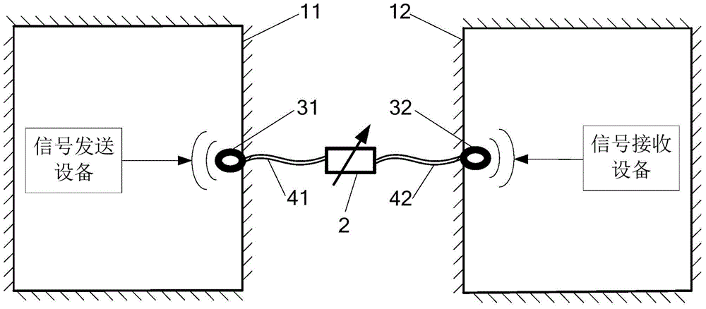
[0040] Please refer tofigure 1 , Embodiment 1 of the present invention is:

[0041] A wireless communication distance testing device, comprising: a first shielding device 11, a second shielding device 12, an amplitude-adjustable signal attenuator 2, a first point source antenna 31, a second point source antenna 32, a first radio frequency cable 41 and the second radio frequency cable 42; the inside of the first shielding device 11 is used to place signal transmitting equipment, and the inside of the second shielding device 12 is used to place signal receiving equipment; the first point source antenna 31 is placed in the first shielding In the device 11, it is used to transmit the original test signal; the second point source antenna 32 is placed in the second shielding device 12, and is used to transmit the test signal; one end of the first radio frequency cable 41 passes through the first shielding device 11 is connected with the first point source antenna 31, and the other e...

Embodiment 2

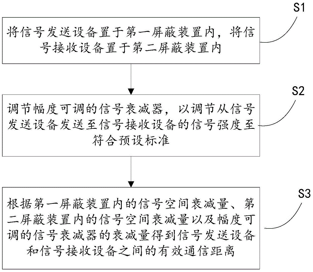
[0043] Please refer to figure 2 , the second embodiment of the present invention is:

[0044] A wireless communication distance testing method, comprising:

[0045] S1. Place the signal transmitting device in the first shielding device 11, and place the signal receiving device in the second shielding device 12;

[0046] S2. Adjust the signal attenuator 2 with adjustable amplitude to adjust the signal strength sent from the signal sending device to the signal receiving device to meet the preset standard, so that the signal strength received by the signal receiving device is reduced to the limit;

[0047] S3. According to the signal space attenuation A1 in the first shielding device 11, the signal space attenuation A2 in the second shielding device 12, and the attenuation A3 of the amplitude-adjustable signal attenuator 2, the difference between the signal sending device and the signal receiving device is obtained. The effective communication distance between; the signal spac...


PUM


Abstract

The invention discloses a radio communication distance testing apparatus and method. The apparatus comprises a first shielding device, a second shielding device and a signal attenuator with an adjustable amplitude. The inner side of the first shielding device is used for placing signal sending equipment. The inner side of the second shielding device is used for placing signal receiving equipment. The input end of the signal attenuator with an adjustable amplitude is used for receiving original test signals sent by the signal sending equipment while the output end is used for providing test signals for the signal receiving equipment. The signal attenuator with an adjustable amplitude is further adjusted to make the strength of signals sent from the signal sending equipment to the signal receiving equipment accord with a preset standard. The effective communication distance between the signal sending equipment and the signal receiving equipment is further acquired according to the signal space attenuation in the first shielding device, the signal space attenuation in the second shielding device and the attenuation of the signal attenuator with an adjustable amplitude.

Description

technical field [0001] The invention relates to the communication field, in particular to a wireless communication distance testing device and method. Background technique [0002] The wireless terminal needs to test the communication distance during the test. The traditional test method needs to carry out the long-distance test in an open space without obstructions. There are many disadvantages in this test method: open environment site requirements are high, and it is difficult to find a site that meets the requirements in urban areas; RF signals in an open environment are easily interfered by signals of the same frequency, which affects the communication distance test; climate factors in an open environment It has a great impact on the test, and the test result is unstable. [0003] The patent document with the application number 201210003088.3 discloses a test system and method for a radio frequency card reader, including: a shielding device for accommodating the radio ...

Claims


Application Information

Patent Timeline
Patent Type & Authority Applications(China)
IPC IPC(8): H04B17/00
Inventor 涂锂程蒋锦扬吴钦钦
Owner FUJIAN LANDI COMML EQUIP CO LTD
Learn More