Circumferential Lever Transmission

A lever transmission, circular technology, applied in the direction of transmission, belt/chain/gear, mechanical equipment, etc., can solve the problem of laborious rotation of the rotating wheel

Inactive Publication Date: 2018-01-30
谢立权
View PDF7 Cites 0 Cited by
  • Summary
  • Abstract
  • Description
  • Claims
  • Application Information

AI Technical Summary

Problems solved by technology

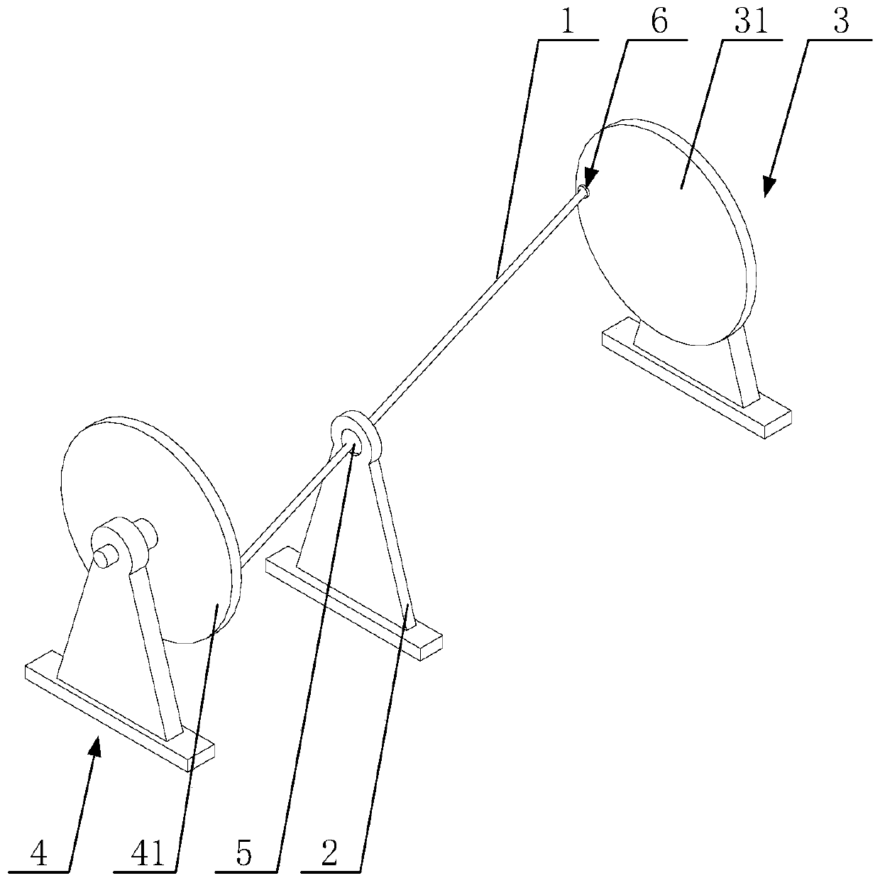
[0005] The purpose of the present invention is to provide a circular lever transmission device to solve the technical problem in the prior art that the power source drives the rotating wheel to rotate more laboriously

Method used


Image

  • Circumferential Lever Transmission

Examples


Embodiment Construction

[0024] The technical solutions of the present invention will be clearly and completely described below in conjunction with the accompanying drawings. Apparently, the described embodiments are some of the embodiments of the present invention, but not all of them. Based on the embodiments of the present invention, all other embodiments obtained by persons of ordinary skill in the art without making creative efforts belong to the protection scope of the present invention.

[0025] In the description of the present invention, it should be noted that the terms "center", "upper", "lower", "left", "right", "vertical", "horizontal", "inner", "outer" etc. The indicated orientation or positional relationship is based on the orientation or positional relationship shown in the drawings, and is only for the convenience of describing the present invention and simplifying the description, rather than indicating or implying that the referred device or element must have a specific orientation, ...


PUM


Abstract

The invention relates to the technical field of circular motion, in particular to a circular rod gear, comprising a dwang, a fixing base, a first connecting mechanism and a second connecting mechanism, wherein the dwang is connected with the fixing base in a rotating manner; one end of the dwang is connected with the first connecting mechanism; the first connecting mechanism is used for connecting with an external power source, so that the external power source can drive both ends of the dwang to do the circular motion; the other end of the dwang is connected with the second connecting mechanism; the second connecting mechanism is used for connecting with an external rotating mechanism, so that the circular motion of the dwang can be converted to a movement form of the external rotating mechanism; a distance from one end, connected with the first connecting mechanism, of the dwang to the fixing base is greater than a distance from the other end, connected with the second connecting mechanism, of the dwang to the fixing base. The circular rod gear provided the invention utilizes a lever principle, so that the power consuming by the external power source due to the fact that the circular rod gear drives the external rotating mechanism is smaller than the power consuming by the external power source due to the fact that the external power source is directly connected with the external power mechanism, and the power source can save power.

Description

technical field [0001] The invention relates to the technical field of circular motion, in particular to a circular lever transmission device. Background technique [0002] Circular motion is the most common curved motion, such as motor rotors, wheels, pulleys, etc. all perform circular motion. Circular motion is divided into uniform circular motion and variable speed circular motion (such as: rope / rod rotating a small ball in a vertical plane, conical pendulum motion in a vertical plane). Among circular motions, the most common and simplest is uniform circular motion. [0003] In terms of how to drive the mechanism to perform circular motion, such as our common bicycle wheel, the rotating shaft is arranged at the center of the rotating wheel, and the rotating shaft is connected to the power source, which drives the rotating shaft to rotate. That is to say, the power source, that is, the foot produces a force on the rotating shaft to make it move in a circle, and drives th...

Claims


Application Information

Patent Timeline
Patent Type & Authority Patents(China)
IPC IPC(8): F16H21/48
CPCF16H21/48
Inventor 谢立权
Owner 谢立权
Why Eureka
Try Eureka